CRT beam current dynamic limitation method and circuit

A technology of dynamic limitation and beam current, which is applied to color TV parts, TV system parts, TVs, etc. It can solve problems such as imperfect protection, ineffective protection of picture tubes, and inability to reflect rapid changes in picture tube beam current. , to achieve the effect of solving beam current overload, accurate and timely sampling, and speeding up the response speed

Inactive Publication Date: 2006-10-11
SHENZHEN TCL NEW-TECH CO LTD
View PDF0 Cites 1 Cited by
  • Summary
  • Abstract
  • Description
  • Claims
  • Application Information

AI Technical Summary

Problems solved by technology

But in this way, due to the time-delay link formed by RC in the circuit, its delay effect makes the reference voltage only reflect changes of lower frequencies, but cannot reflect the fast-changing part of the image
[0004] In addition, due to the parasitic capacitance of the EHT generator itself and the additional filter capacitor due to the stability requirements of the EHT, the reference signal obtained by the traditional ABL circuit has actually been filtered by the energy storage element in the circuit, so it can only reflect relatively small The brightness of the image changes slowly, but cannot reflect the brighter picture that appears locally, that is to say, the traditional ABL circuit only appears in the whole image when a larger area is brighter, that is, only when the average beam current Only when the value is relatively large, it acts as a limit
[0005] Through the above analysis, it shows that the above-mentioned sampling has obvious limitations, so the reference voltage taken out can only reflect the slow change of the picture tube beam current and cannot reflect the rapid change of the picture tube beam current
[0006] For another case, when a scene with local high brightness appears in the image, the beam current of the picture tube may be overloaded instantaneously at this time, and the protection circuit should play a control role, but because the average value of the beam current is not large at this time, so The traditional ABL circuit does not limit it, that is to say, in this case, the traditional ABL circuit cannot provide effective protection for the picture tube, so its protective effect is obviously imperfect

Method used


Image

  • CRT beam current dynamic limitation method and circuit
  • CRT beam current dynamic limitation method and circuit
  • CRT beam current dynamic limitation method and circuit

Examples


Embodiment Construction

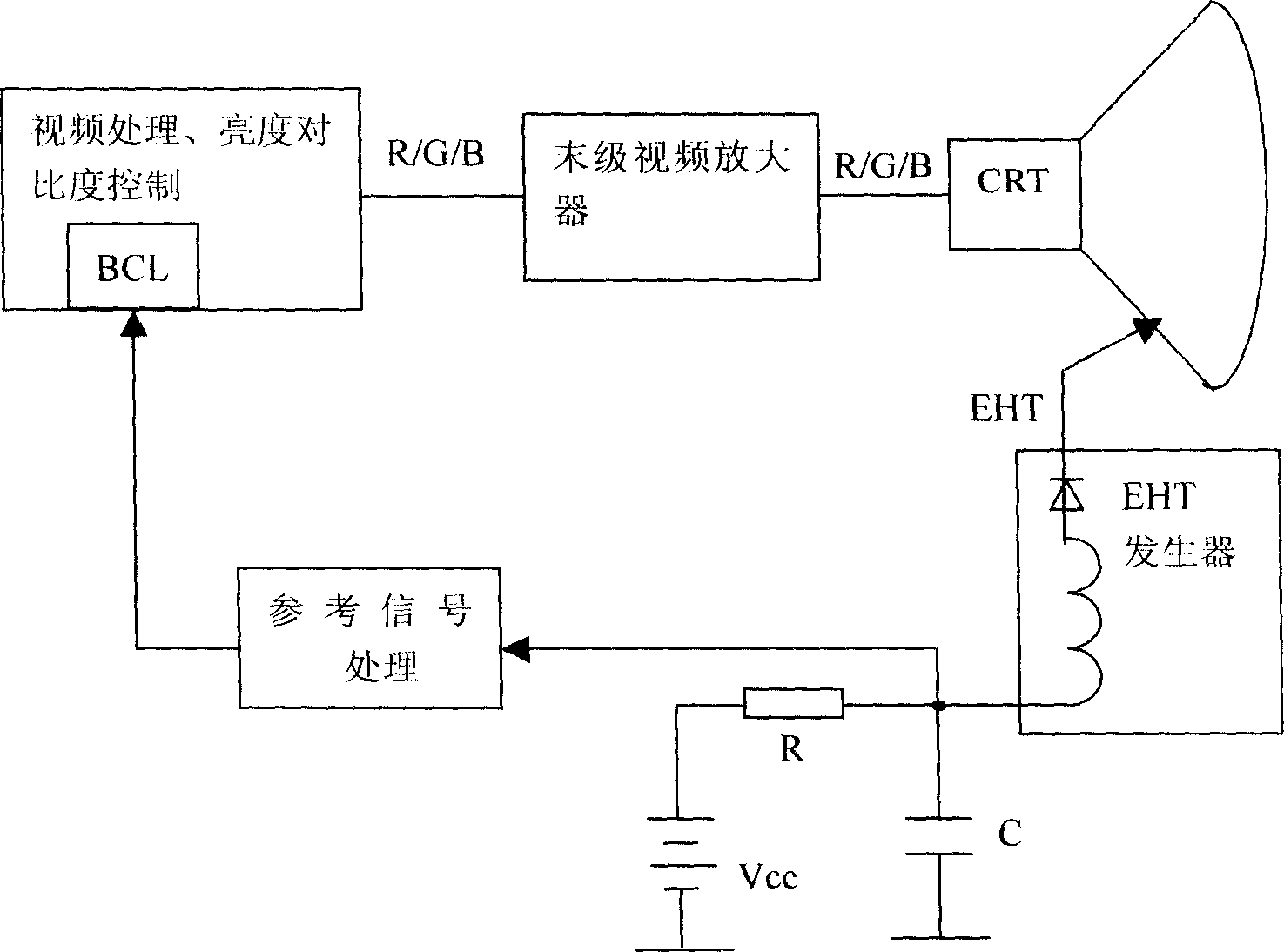
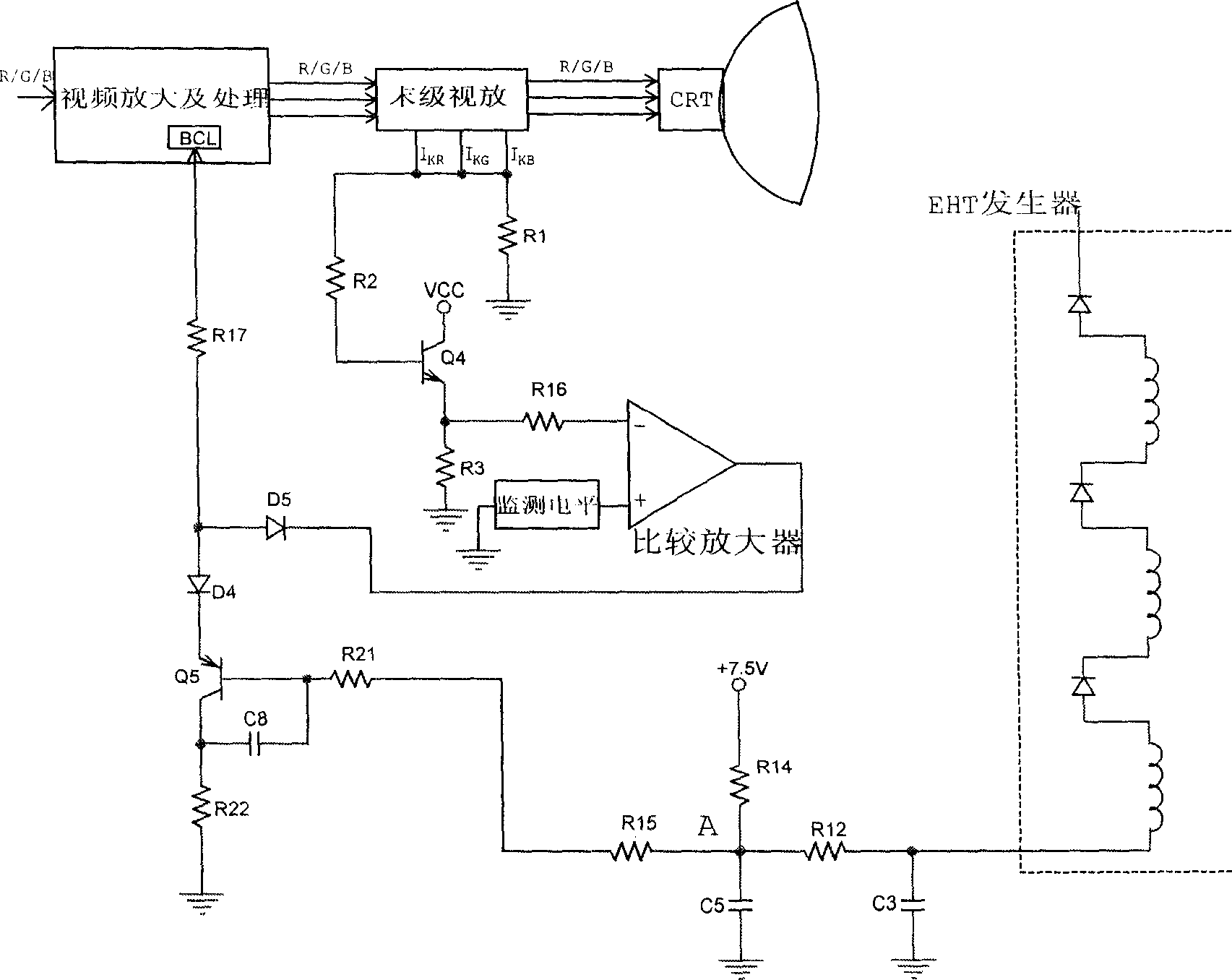
[0041] Such as figure 2 , the sampling resistor R is connected to the cathode circuit of the kinescope, and the cathode of the kinescope is also the driving object of the final video amplifier. Driven by the final video amplifier, the cathode current flows through the sampling resistor R to form a reference voltage. The cathode current of the kinescope is the beam current of the kinescope. Since there is no energy storage element in the sampling link, the reference voltage obtained in this way can truly and quickly reflect the beam current corresponding to the instantaneous brightness of the image. We let it be reference signal 1. The acquisition of the reference signal 2 reflecting the average value of the picture tube bundle current has been described in the previous patent documents of our company.

[0042]A comparative amplifier is composed of an operational amplifier, which is used for overload detection. The reference signal 1 is input to the inverting input terminal o...


PUM


Abstract

The presented circuit to dynamic limit CRT beam current comprises a extra-high voltage generator, a CRT, a video processing circuit, a end-stage amplification circuit, a sample circuit, a comparison amplifier, ad a adder. This invention speedups response rate of ABL, and provides enough protection for picture tube.

Description

technical field [0001] The invention relates to a protection method for a CRT picture tube, in particular to a method for dynamically limiting the picture tube beam current combined with an original compensation method and a circuit thereof. Background technique [0002] Such as figure 1 , the traditional automatic beam current limiting (ABL) circuit uses the current of the extremely high voltage (EHT) generator as a reference signal. The electrons emitted by the cathode of the picture tube flow under the drive of the extreme high voltage (EHT), so the current of the EHT generator reflects the size of the beam current, and it flows through the sampling resistor R to form a reference voltage signal. When the reference voltage signal exceeds the preset value, it is sent to the execution circuit (ie, BCL circuit) to limit the value of contrast and brightness, and finally achieve the purpose of limiting the beam current and protecting the picture tube. [0003] In order to ens...

Claims


Application Information

Patent Timeline
IPC IPC(8): H04N5/59
Inventor 黄凯华樊伟齐
Owner SHENZHEN TCL NEW-TECH CO LTD
Why Eureka
Try Eureka