Color image forming apparatus

A color image and image technology, applied in the field of color image forming devices, can solve the problems of complex structure of processing system, difficulty in obtaining full-color images, difficulty and the like

Inactive Publication Date: 2010-11-03
CANON KK
View PDF5 Cites 0 Cited by
  • Summary
  • Abstract
  • Description
  • Claims
  • Application Information

AI Technical Summary

Problems solved by technology

But on the other hand, there is also such a problem: due to the deviation of the position accuracy or diameter of each photoreceptor, the position accuracy deviation of the optical system, etc., the color registration deviation caused by the position deviation of each color on the transfer material occurs, Difficulty obtaining high-quality full-color images
[0007] However, with the method disclosed in Patent Document 1, problems such as the following arise
[0008] First, in order to correct the optical path of the optical system, it is necessary to mechanically operate the correcting optical system including the light source, the f-θ lens, the reflection mirror in the optical path, etc., to keep the position of the toner image consistent with the test. For this reason, it is necessary to High-precision moving parts, resulting in increased costs
Furthermore, it takes a lot of time until the calibration is completed, so frequent calibration cannot be performed, and sometimes the deviation of the optical path length changes with time due to mechanical temperature rise. In this case, it is very difficult to prevent color registration deviation by correcting the optical path of the optical system.
Second, when correcting the writing start position of the image, the position deviation of the left end and the upper left can be corrected, but the tilt of the optical system and the magnification deviation caused by the deviation of the optical path length cannot be corrected
Therefore, there is a problem that the amount of calculation increases and the configuration of the processing system becomes complicated.

Method used


Image

  • Color image forming apparatus
  • Color image forming apparatus
  • Color image forming apparatus

Examples


no. 1 Embodiment approach

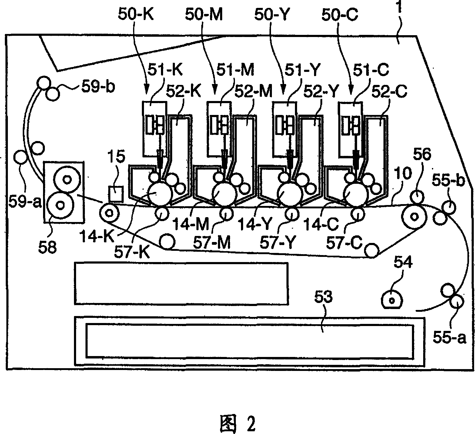
[0058] figure 2 It is a schematic cross-sectional view showing the configuration of the color image forming apparatus in this embodiment. The illustrated color image forming apparatus 1 is, for example, a so-called tandem color laser printer having four photosensitive drums. In this color image forming apparatus 1 , a transfer material cartridge 53 is attached to the lower part of the right side of the main unit. The transfer materials placed in the transfer material cassette 53 are taken out one by one by the paper feed roller 54, and sent to the image forming section by the pair of conveying rollers 55-a, 55-b. In the image forming section, the transfer conveyor belt 10 that conveys the transfer material is driven by a plurality of rotating rollers along the transfer material conveying direction ( figure 2 The transfer material is electrostatically adsorbed on the transfer conveyor belt 10 at its most upstream portion.

[0059] In the color image forming apparatus 1 , f...

no. 2 Embodiment approach

[0138] In the second embodiment, for example, when switching the density of gradation correction with 3 pixels and 4 levels, at (a) the position where the coordinate transformation is performed, (b) the position one pixel before the position where the coordinate transformation is performed, ( c) The above-mentioned switching is performed at a position 2 pixels before the position where the coordinate transformation is performed.

[0139] Therefore, the color misregistration position calculation units 407C, 407M, 407Y, and 407K calculate the position one pixel before the position where the coordinate transformation is performed and the position two pixels before the position where the coordinate conversion is performed, respectively.

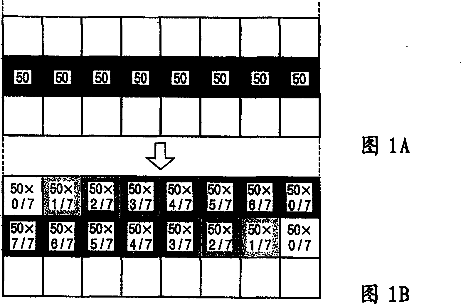
[0140] FIG. 9 is a diagram explaining the color misregistration correction performed by the gray scale correction unit 804 which is smaller than the pixel unit. By adjusting the exposure ratios of dots before and after the sub-scanning direction,...

no. 3 Embodiment approach

[0177] According to the above-mentioned Patent Document 2 (Japanese Patent Laid-Open No. 8-85237 ), the coordinate positions of image data for outputting each color are corrected for an image subjected to halftone processing. For this reason, when dithering is performed, the halftone dot reproducibility of the halftone image deteriorates. As a result, color unevenness may occur, and moiré may become conspicuous. Furthermore, when such non-uniform density values ​​are periodically repeated, there is a problem that moiré is conspicuous and a good color image cannot be obtained. The third embodiment solves such a problem.

[0178] The color image forming apparatus according to the embodiment of the present invention is also a 4-drum color laser printer, citing figure 2 .

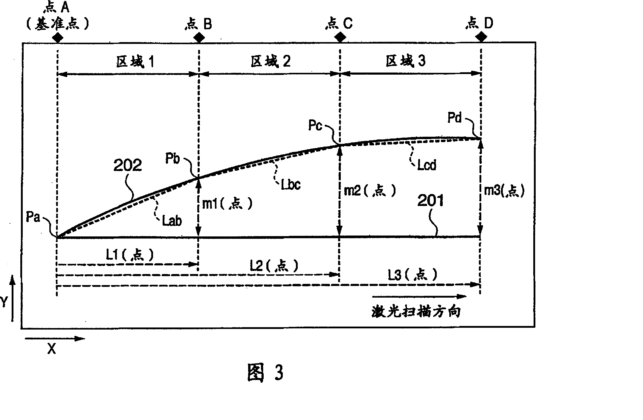
[0179] Figure 10 It is a conceptual diagram explaining the variation of the main scanning line scanned on each photosensitive drum 14 (for example, the photosensitive drum 14-C for cyan) serving as an ima...


PUM


Abstract

A color image forming apparatus of a so-called tandem type which has image forming units in correspondence with colors is provided. In the color image forming apparatus, a color discrepancy amount storage unit stores information of a color discrepancy amount of each of the image forming units, which is measured in advance. A first color discrepancy correcting unit performs color discrepancy correction in a pixel unit by performing coordinate conversion of bitmap data to be printed based on the information of the color discrepancy amount stored in the color discrepancy amount storage unit. A second color discrepancy correcting unit performs color discrepancy correction in less than a pixel unit by performing tone correction of the bitmap data corrected by the first color discrepancy correcting unit based on the information of the color discrepancy amount stored in the color discrepancy amount storage unit.

Description

technical field [0001] The present invention relates to a color image forming apparatus, and more particularly to an electrophotographic color image forming apparatus. Background technique [0002] An electrophotographic color image forming apparatus is known. It forms an image in the following way: a photoreceptor is developed in various colors with multiple developers, and the image of each color is superimposed on a transfer material through repeated exposure-development-transfer process. A color image is formed and fixed to obtain a full-color image. [0003] However, this method has the disadvantage that in order to obtain one printed image, the image forming process needs to be repeated three times (four times in the case of using black), and it takes a lot of time to form an image. [0004] As a method to overcome this disadvantage, there is a so-called tandem method in which a plurality of photoreceptors are used, and images obtained for each color are sequentially...

Claims


Application Information

Patent Timeline
Patent Type & Authority Patents(China)
IPC IPC(8): G03G15/01G03G15/04G03G13/00H04N1/60G03G15/00
Inventor 户岛研三北村宏记秋叶喜之高田力中村秀一山本雄介本山昌尚秋山武士永冈右明
Owner CANON KK
Why Eureka
Try Eureka