Heating cooker
A technology of cooker and heating chamber, which is applied in the directions of heating method, induction heating, electric heating fuel, etc., can solve the problems of poor usability of heating cooker, inability to heat and cook, and narrow horizontal width, etc., and achieves the improvement of utilization value. Effect
- Summary
- Abstract
- Description
- Claims
- Application Information
AI Technical Summary
Problems solved by technology
Method used
Image

Examples
Embodiment approach 1
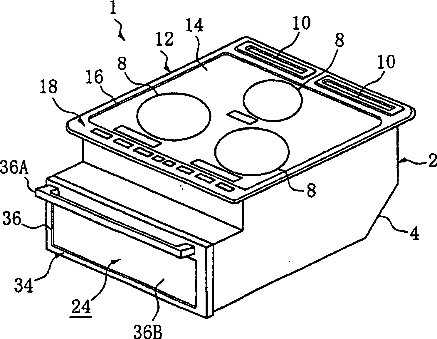
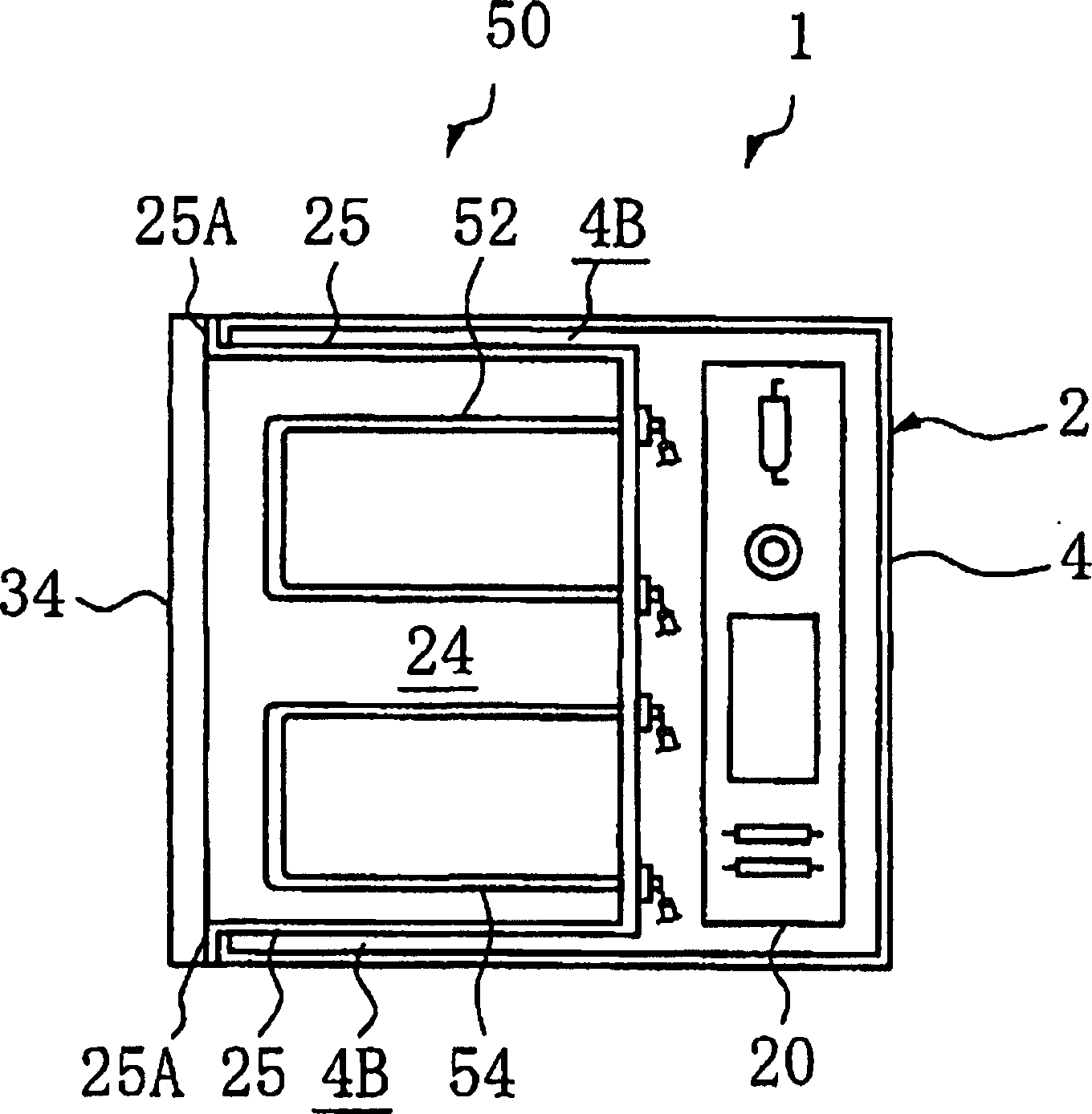
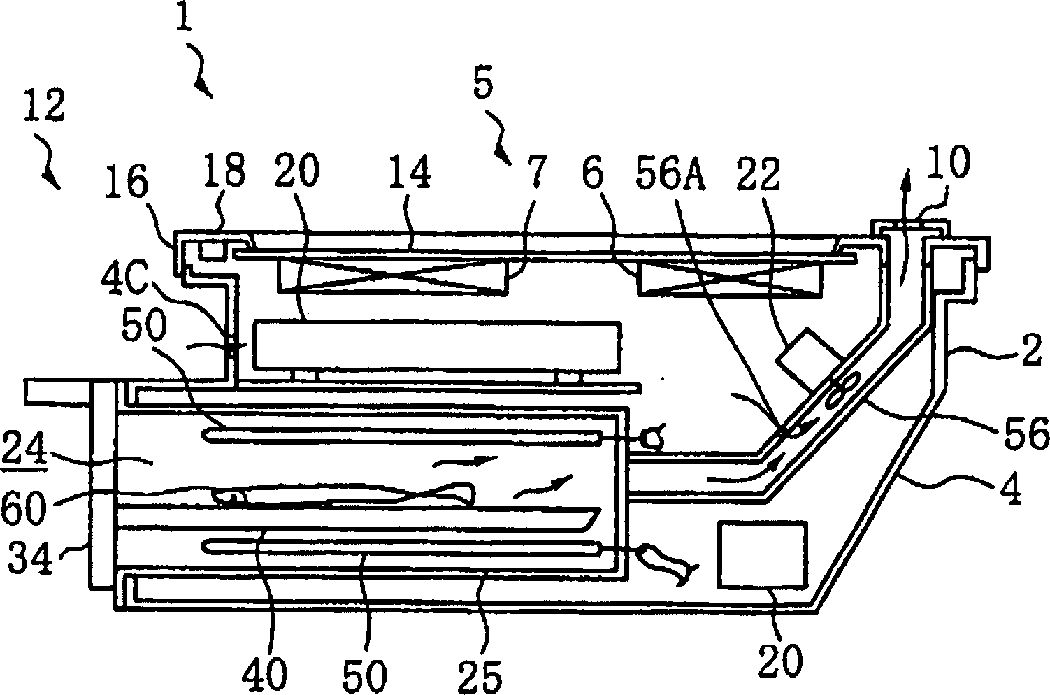
[0028] Hereinafter, the present invention will be described in detail according to one embodiment of the present invention. respectively expressed as figure 1 It is a perspective view of the heating cooker 1 in this embodiment, figure 2 It is a plan view of the main part of the heating cooker 1 in this embodiment, image 3 It is a longitudinal sectional view of the heating cooker 1 in this embodiment, Figure 4 It is a perspective view of the drawer 34 which comprises the heating chamber 24 of the heating cooker 1 in this embodiment.
[0029] In this embodiment, the heating cooker 1 such as figure 1 As shown, a main body case 4 is provided outside the cooker main body 2 , and the top opening of the main body case 4 is covered by a top plate body 12 . The top plate body 12 is composed of a flat top plate 14 made of a non-magnetic material such as heat-resistant glass, and a frame 16 arranged around the top plate 14 . On the lower surface of the top plate 14 , a heating ...
Embodiment approach 2
[0041] The heating cooker 1 in this embodiment has substantially the same structure as the above-mentioned embodiment. Next, the different parts will be described. In addition, the same code|symbol is attached|subjected to the same part as the above-mentioned embodiment, and the description is abbreviate|omitted. Figure 6 It is a perspective view of a drawer 34 according to another embodiment of the present invention, Figure 7 It is the top view which divided|segmented the heating chamber. That is, a partition plate 46 is vertically provided between the main tray 42 and the sub-tray 44 constituting the tray 40 installed on the drawer 34 . The partition plate 46 is detachably attached, and the inside of the heating chamber 24 can be divided into a plurality (two in the embodiment) by the partition plate 46 .
[0042] Thus, when drawer 34 is inserted into heating chamber 24 , heating chamber 24 is divided into main heating chamber 26 on the left side of partition 46 and aux...
Embodiment approach 3
[0046] The heating cooker 1 in this embodiment has substantially the same structure as the above-mentioned embodiment. Hereinafter, the different parts will be described. In addition, the same code|symbol is attached|subjected to the same part as the above-mentioned embodiment, and the description is abbreviate|omitted. Figure 8 It is a perspective view of a heating cooker 1 according to another embodiment of the present invention, Figure 9 It is a perspective view of the main tray 42 constituting the drawer 34 of the heating cooker 1, Figure 10 It is a perspective view of the auxiliary tray 44 which is a drawer of the heating cooker 1 .
[0047] In this embodiment, a storage chamber 32 is provided adjacent to the main heating chamber 26 formed in the main body case 4 , and the front opening of the storage chamber 32 is closed openably and closably by a storage cover 33 . That is, the cooker main body 2 (main body case 4) is opened from the left end to the right end with...
PUM
 Abstract
Description
Claims
Application Information
 - R&D Engineer
- R&D Manager
- IP Professional
- Industry Leading Data Capabilities
- Powerful AI technology
- Patent DNA Extraction
Browse by: Latest US Patents, China's latest patents, Technical Efficacy Thesaurus, Application Domain, Technology Topic.
© 2024 PatSnap. All rights reserved.Legal|Privacy policy|Modern Slavery Act Transparency Statement|Sitemap