Cleaning device and cleaning method

The technology of a washing device and a washing method, which is applied in the directions of cleaning methods and utensils, chemical instruments and methods, and cleaning methods using liquids, etc., can solve problems such as difficulty in properly discharging the container 102 , uniform supply of cleaning liquid, and difficulty in cleaning end faces, etc.

Inactive Publication Date: 2006-10-04
KAIJOO KK
View PDF3 Cites 3 Cited by
  • Summary
  • Abstract
  • Description
  • Claims
  • Application Information

AI Technical Summary

Problems solved by technology

[0007] But when Figure 24 In the washing apparatus 100 shown in the rotating mode, since the washing liquid injected onto the surface 101A of the wafer 101 spreads to the back surface 101B of the wafer 101 during washing, the wafer is clamped by the chuck of the wafer stage 103, etc. 101 end face, so it is difficult to clean the end face connected with the chuck, etc.
[0008] In addition, in the cleaning device 100 described above, since the wafer 101 is installed in a horizontal state, the installation space of the cleaning device 100 as a whole becomes large.
Furthermore, the washing apparatus 100 has the wafer stage 103 and the rotating shaft 104 as the rotating structure, so the number of parts increases and the adjustment of these rotating structures requires a lot of time.
[0009] In addition, in the cleaning apparatus 100 described above, since the cleaning liquid and the like are supplied to the rotating wafer 101 by the supply nozzle 105, it is difficult to uniformly supply the cleaning liquid to the surface 101A of the wafer 101, and it is difficult to control the temperature of the cleaning liquid and the like.
[0010] Furthermore, in the cleaning apparatus 100 described above, since the wafer 101 is rotated by the wafer stage 103, it is difficult to properly discharge the wafer 101 into the container 102 due to the air flow (turbulent flow, etc.) The unwanted gas in the cup tube (cup) 109 in

Method used


Image

  • Cleaning device and cleaning method
  • Cleaning device and cleaning method
  • Cleaning device and cleaning method

Examples


no. 1 Embodiment approach

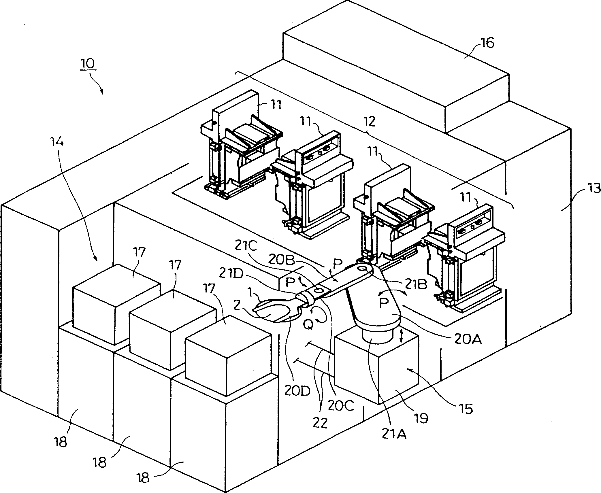
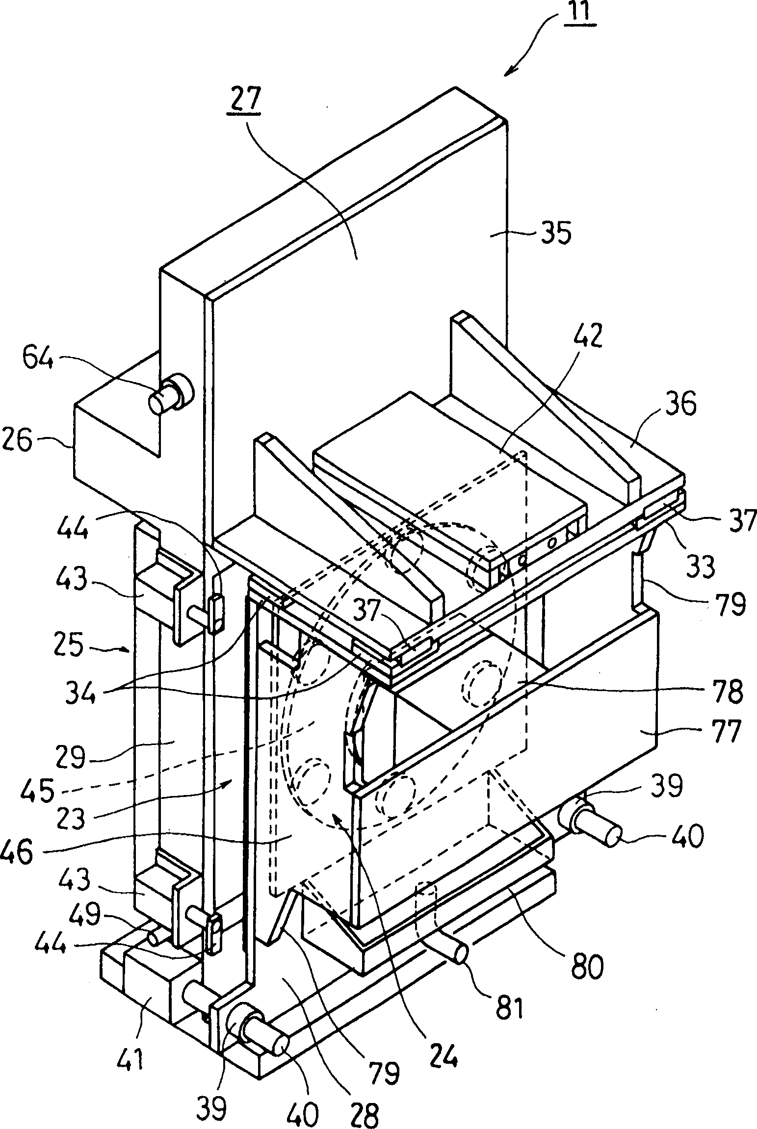
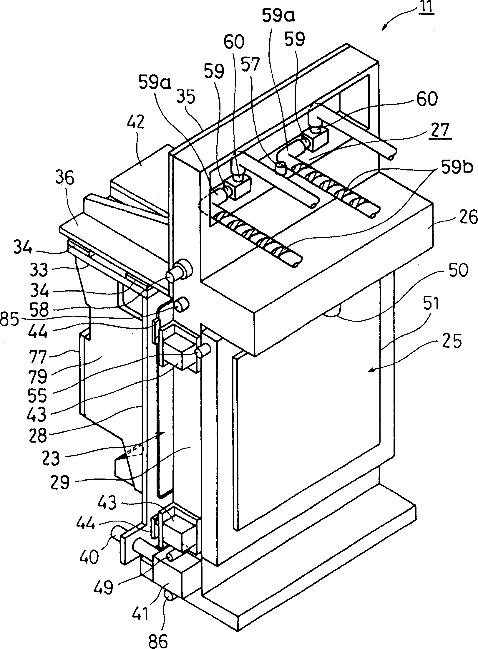
[0132] figure 1 It is a perspective view of a washing facility in which the washing apparatus according to the first embodiment of the present invention is arranged. figure 2 yes figure 1 Oblique front perspective view of the washing machine in standby state. image 3 yes figure 1 Oblique rear perspective view of the washing machine in its standby state. Figure 13is to illustrate figure 2 A schematic cross-sectional view of the principle of the washing device.

[0133] figure 1 The shown cleaning equipment 10 includes a cleaning device arrangement part 12 provided with a plurality of cleaning devices 11 (described in detail later) for cleaning semiconductor substrates (for example, wafers 1 ) as objects to be processed, and adjacent to the cleaning device arrangement part 12. The chemical solution supply part 13 arranged, the wafer supply and discharge part 14 arranged at the position facing the above-mentioned chemical solution supply part 13, the transfer robot ...

no. 2 Embodiment approach

[0201] The second embodiment ( Figure 18-23 )

[0202] Figure 18 It is an oblique front perspective view of a washing machine according to a second embodiment of the present invention. Figure 19 yes Figure 18 A side view of the cleaning apparatus with wafers carried in and out. Figure 20 yes Figure 18 A front view of the cleaning device for wafer cleaning and other processing states. Figure 21 is along Figure 20 View taken by arrow VII in . Figure 22 is to illustrate Figure 18 A brief structural cross-sectional view of the principle of the washing device. Figure 23 yes Figure 22 Partially enlarged cross-sectional view. In the second embodiment, the same parts as those in the first embodiment are denoted by the same symbols, and description thereof will be omitted.

[0203]In the cleaning device 90 of the second embodiment described above, the spot facing surface 70 provided around the opening 30 of the front wall 28 in the first embodiment and the plug 7...


PUM


Abstract

The invention provides a cleaning device for cleaning or rinsing a wafer disposed in a cleaning bath by cleaning fluid in the cleaning bath including a front wall that configures the cleaning bath by being in abutment with a device body and is formed with an opening corresponding to a contour of the target object; a wafer holding device being capable of holding a rear face of the target object carried into the inner side of the one side wall through the opening from the outside of the one side wall and holding the target object in a vertically upright position; and a pins provided on a circumference of the opening on an inner surface of the one side wall for defining a clearance between the wafer and the circumference of the opening by being in contact with the rear face of the target object.

Description

technical field [0001] The present invention relates to a cleaning device and a cleaning method for cleaning objects to be processed in a washing tank, and more particularly to a cleaning device and a cleaning method for simultaneously cleaning the surface and / or back of semiconductor substrates such as wafers one by one. Background technique [0002] In the semiconductor manufacturing process, the washing apparatus for washing, rinsing, and drying semiconductor substrates such as wafers one by one generally adopts the rotation method described in Patent Document 1. Such as Figure 24 As shown, in such a washing apparatus 100, a wafer stage 103 for clamping the end surface of a wafer 101, etc., is provided in a cylindrical container (chamber) 102, and the wafer stage is supported by a rotating shaft 104. 103. The rotating shaft 104 is connected to a motor (not shown), and driven by the motor, the wafer 101 clamped on the wafer carrier 103 is rotated. [0003] There is a su...

Claims


Application Information

Patent Timeline
Patent Type & Authority Applications(China)
IPC IPC(8): B08B3/04B08B3/12B08B13/00F26B3/02B08B11/00B08B11/02H01L21/304
Inventor 泽木晃河野通久
Owner KAIJOO KK
Why Eureka
Try Eureka