
Action locking gear of isolation switch

A locking mechanism and isolating switch technology, which is applied in the direction of electric switches, electrical components, circuits, etc., can solve the problems of poor safety of isolating switches, achieve the effect of convenient unlocking, avoiding misoperation, and improving safety

Active Publication Date: 2006-09-20
ZHEJIANG CHINT ELECTRIC CO LTD
View PDF0 Cites 8 Cited by
  • Summary
  • Abstract
  • Description
  • Claims
  • Application Information

AI Technical Summary

Problems solved by technology

[0003] The present invention aims to solve the problem of poor safety of the existing isolating switch, and aims to provide an action locking mechanism to improve the safety of the isolating switch in use

Method used


Image

  • Action locking gear of isolation switch
  • Action locking gear of isolation switch
  • Action locking gear of isolation switch

Examples


Embodiment Construction

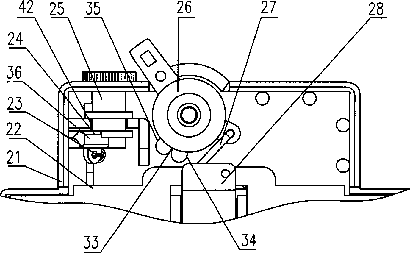
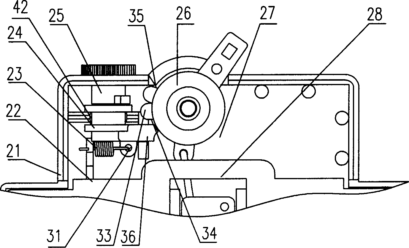
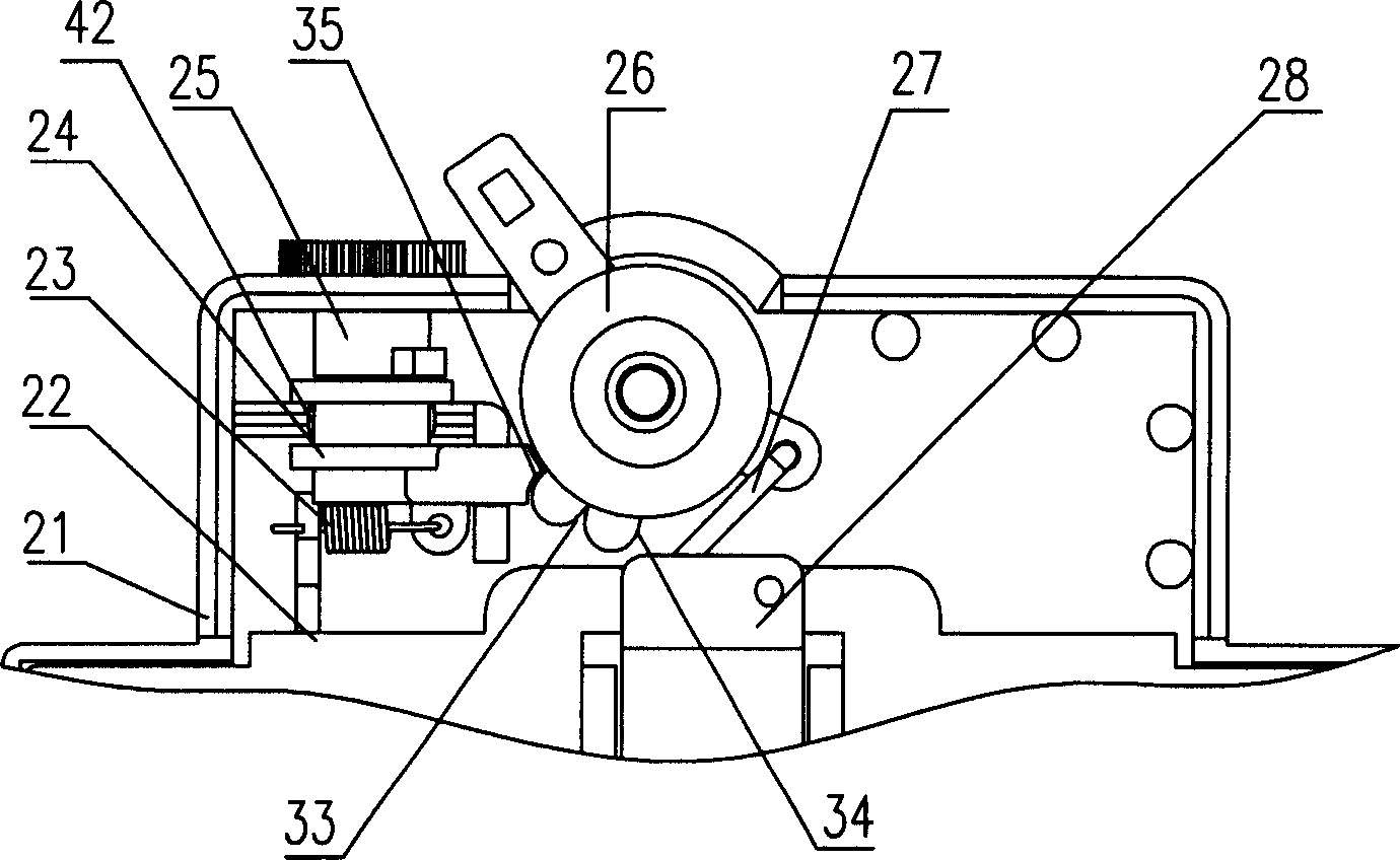
[0015] Referring to the accompanying drawings, the isolating switch itself has an action mechanism composed of a housing 21, a partition 22, a handle 26, a "U" shaped rod 27 and a contact system 28. The action locking mechanism of the present invention includes a knob 25, a stopper 24 and Spring 23. The main parts of the knob 25 and the stopper 24 are cylindrical, and are arranged in the circular groove 42 of the isolating switch housing 21 . The knob 25 is sleeved on the square column 38 provided on the stopper 24 through the square hole 39 opened thereon, so that the knob 25 is turned, and the stopper 24 will move in unison. The stopper 24 is also provided with a stop arm 36, and the handle 26 of the isolating switch is provided with a boss 33 matched with the stop arm 36, and the boss 33 is provided with The first stop surface 34 corresponds to the closed state and the second stop surface 35 corresponds to the open state. The second stop surface 35 is a convex arc surface...


PUM


Abstract

The locking gear includes knob, locking piece, and spring. The knob is sheathed on the locking piece. The locking piece also possesses a stopping arm. Being cooperated with the stopping arm, bosses on handle of isolating switch locks the switch at connection or disconnection state. One end of the spring is setup at the stopping arm; and the other end of the spring is setup at a fixed part of the isolating switch. The disclosed locking gear locks handle at connection or disconnection state so as to avoid error operation, and increase safety of isolating switch. Using rotational knob interlocks the locking piece so as to be able to release from locking expediently.

Description

technical field [0001] The invention relates to a mechanism of a low-voltage electrical appliance, in particular to an action locking mechanism of an isolating switch. Background technique [0002] Most of the existing small modular isolating switches adopt direct-acting double-breakpoint structure without action locking function. The handle of this isolating switch is prone to misoperation, which will bring potential safety hazards. Contents of the invention [0003] The invention aims to solve the problem of poor safety of the existing isolating switch, and aims to provide an action locking mechanism to improve the safety of the isolating switch in use. The technical solution adopted to solve the above problems is: an action locking mechanism of a disconnector, including a knob, a stopper and a spring, the knob is sleeved on the stopper, and the stopper is also provided with A stop arm, the handle of the isolating switch is provided with a boss that cooperates with the...

Claims


Application Information

Patent Timeline
Patent Type & Authority Applications(China)
IPC IPC(8): H01H21/02H01H21/18H01H9/20
Inventor 严鹏斌王先锋陈建斌
Owner ZHEJIANG CHINT ELECTRIC CO LTD
Learn More