
Coupler with double-row chains

A technology of couplings and chains, applied in the direction of couplings, sliding couplings, mechanical equipment, etc., can solve problems such as time delay, troublesome process, inconvenient use, etc., to improve safety reliability and ensure accuracy , the effect of improving work efficiency

Inactive Publication Date: 2006-09-20
ZHONGYUAN ENGINEERING COLLEGE
View PDF0 Cites 7 Cited by
  • Summary
  • Abstract
  • Description
  • Claims
  • Application Information

AI Technical Summary

Problems solved by technology

[0002] There are many types of couplings, which are widely used in papermaking, glass, rubber and other chemical, light industry and construction machinery fields. However, the torque of the coupling sometimes changes during work. If there is no Overload protection, it is easy to burn out the drive motor, so the safety coupling came into being. In the mechanical design manual, there is a safety pin coupling, which uses a cylindrical pin as a load-bearing element. When the working load exceeds the allowable value, The cylindrical pin is automatically cut off, thereby cutting off the transmission between the working machine and the prime mover, which can play the role of overload protection, but because it is a rigid connection, the cylindrical pin must be reinstalled before restoring the transmission; because it is too sensitive to instantaneous overload, it is easy to cause Unnecessary damage to the cylindrical pin; when the limited torque changes, the corresponding cylindrical pin needs to be replaced, the process is cumbersome and time-consuming, and it is very inconvenient to use

Method used


Image

  • Coupler with double-row chains

Examples


Embodiment Construction

[0011] Below in conjunction with accompanying drawing, the present invention will be further described:

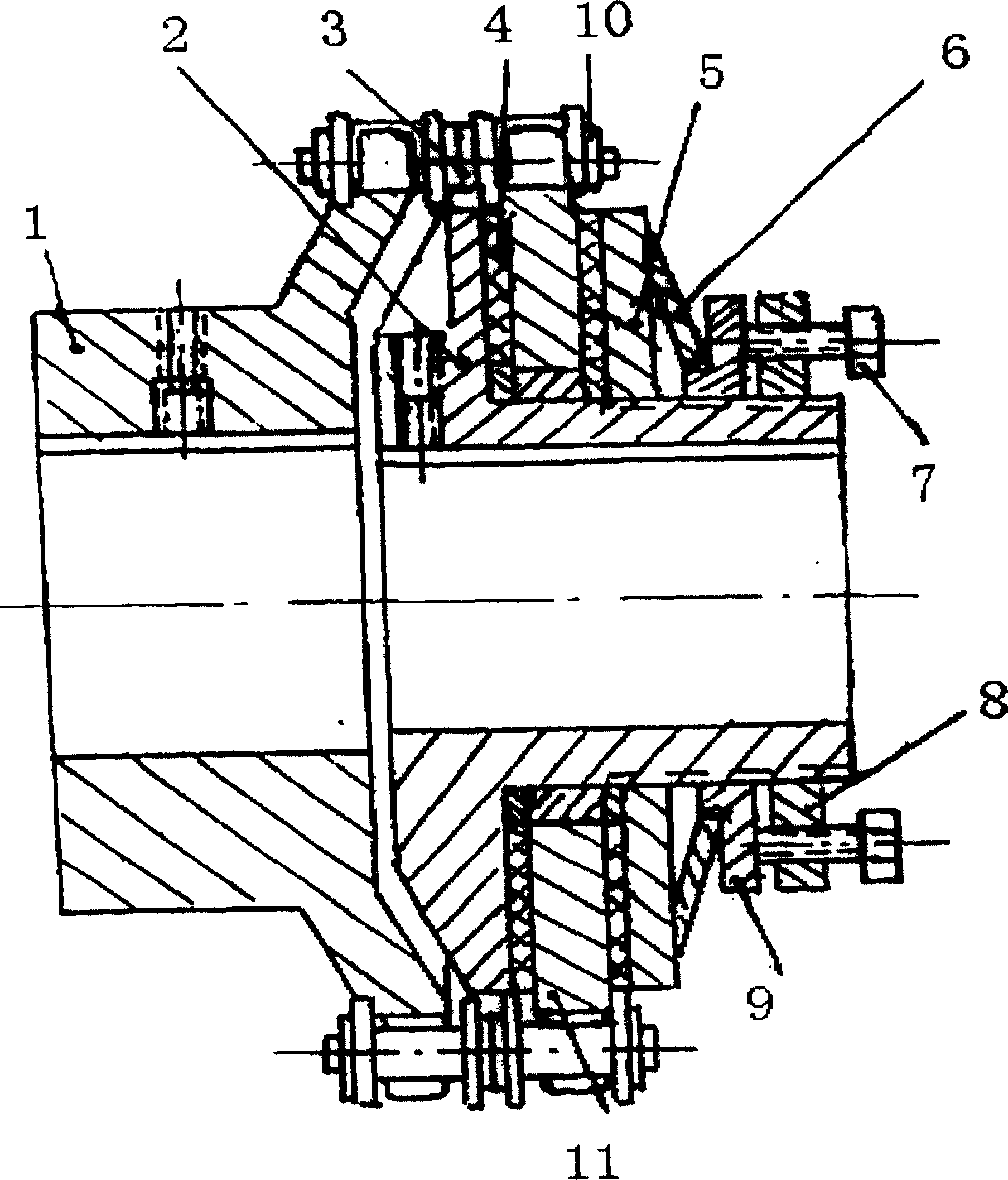
[0012] Such as figure 1 As shown: the present invention includes a driven sprocket 1 connected to the input shaft of the working machine, a sleeve 2 connected on the prime mover motor, and a plate sprocket 11 is also set on the sleeve 2, and the driven sprocket 1 and the plate sprocket The ring-shaped double-row chain 3 is set between the sprockets 11, there is an A friction plate 4 between the plate sprocket 11 and the sleeve 2, there is a B friction plate 10 between the plate sprocket 11 and the pressure plate, and the buffer member 6 is set on the pressure plate 5 Between the guide plate 9 , the outer side of the guide plate 9 abuts against the adjustment piece installed on the sleeve 2 .

[0013] Friction plate, plate sprocket 11 , pressure plate 5 , buffer member 6 and guide plate 9 are all sleeved on the sleeve 2 . A shaft sleeve is also provided between the plate ...


PUM


Abstract

The present invention discloses a torque adjustable coupler. It includes the following several portions: driven chain wheel coupled with working machine input shaft, sleeve coupled on the power motor, on the sleeve are successively cover-connected friction disk A, plate type chain wheel, friction disk B, pressure plate, Belleville-type spring and guide plate. The guide plate is connected with a regulation screw by means of a regulation nut, and on the driven chain wheel and the plate-type chain wheel two rows of chains are respectively cover-connected. Said invention also provides the concrete working principle of said coupler. Said invention not only raises the safety reliability of equipment operation, but also raises the working efficiency of said equipment.

Description

Technical field: [0001] The invention relates to connecting parts in the field of mechanical transmission, in particular to a torque-adjustable shaft coupling with double-row chains. Background technique: [0002] There are many types of couplings, which are widely used in papermaking, glass, rubber and other chemical, light industry and construction machinery fields. However, the torque of the coupling sometimes changes during work. If there is no Overload protection, it is easy to burn out the drive motor, so the safety coupling came into being. In the mechanical design manual, there is a safety pin coupling, which uses a cylindrical pin as a load-bearing element. When the working load exceeds the allowable value, The cylindrical pin is automatically cut off, thereby cutting off the transmission between the working machine and the prime mover, which can play the role of overload protection, but because it is a rigid connection, the cylindrical pin must be reinstalled befor...

Claims


Application Information

Patent Timeline
Patent Type & Authority Applications(China)
IPC IPC(8): F16D7/00
Inventor 梁睦李铬
Owner ZHONGYUAN ENGINEERING COLLEGE
Learn More