Method for controlling battery charging by gas sensor
A gas sensor and battery charging technology, which is applied in secondary battery charging/discharging, secondary battery, secondary battery repair/maintenance, etc., can solve problems such as wasting energy, shortening battery life, and battery overcharging
- Summary
- Abstract
- Description
- Claims
- Application Information
AI Technical Summary
Problems solved by technology
Method used
Image
Examples
example 1
[0064] Example 1 A gas pressure sensor is used to detect the internal pressure change of a cylindrical SC-QNY3 nickel metal hydride (MH-Ni) battery 3C during charging.
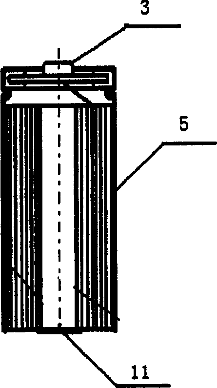
[0065] image 3 It is a schematic diagram of a cylindrical battery external gas pressure sensor device. Compared with the built-in pressure sensor 1 , the external pressure sensor 11 reflects the internal pressure of the battery under test 2 by detecting the small deformation of the bottom of the battery under test 2 during the charging and discharging process of the battery under test 2 . When the external pressure sensor 11 is used, it is only necessary to connect the part of the battery 2 under test with a larger deformation to the external pressure sensor 11, and the connection method is as follows:
[0066] The pressure strain gauge of the external pressure sensor 11 is fixed to the outside of the bottom of the cylindrical battery under test 2 or the side of the square battery with special glue. The pos...
example 2
[0069] Example 2 The internal oxygen content of the square nickel metal hydride (MH-Ni) battery QNF14 changes at 5A during charging.
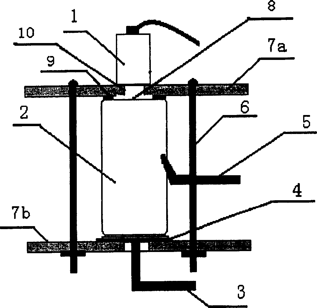
[0070] Figure 4 It is a schematic diagram of the gas sensor (pressure or oxygen content) device inside the prismatic battery. Among them, the gas sensor 1 can be tightened and compressed by sealing rings and ribs at the position of the safety valve of the square battery under test 2, and can also be rounded at a position other than the safety valve, and the round mouth also needs to be machined. The thread is so that when the gas sensor 1 is installed, the sealing ring and the thread are tightened to compress the seal. The positive pole 3a and the negative pole 5a of the battery 2 under test are respectively connected to two output terminals of the charging device.
[0071] Image 6 It represents the internal gas change of the square nickel metal hydride (MH-Ni) QNF14 battery during the charging process. When charging for about 170min, the...
example 3
[0072] Example 3 During the 5A charging process of the square nickel-metal hydride (MH-Ni) battery QNF14, the state of charge (SOC) of the battery is estimated from the oxygen content in the internal gas.
[0073] from Figure 7 It can be seen that at 20°C, the oxygen content of the square nickel metal hydride (MH-Ni) QNF14 battery during the charging process has a good correspondence with the charging power, so the state of charge (SOC) of the battery can be judged according to the oxygen content in the battery. ).
PUM
 Abstract
Description
Claims
Application Information
 - R&D
- Intellectual Property
- Life Sciences
- Materials
- Tech Scout
- Unparalleled Data Quality
- Higher Quality Content
- 60% Fewer Hallucinations
Browse by: Latest US Patents, China's latest patents, Technical Efficacy Thesaurus, Application Domain, Technology Topic, Popular Technical Reports.
© 2025 PatSnap. All rights reserved.Legal|Privacy policy|Modern Slavery Act Transparency Statement|Sitemap|About US| Contact US: help@patsnap.com


