
Roller type curve design method in thin narrow material smoothing and rolling process

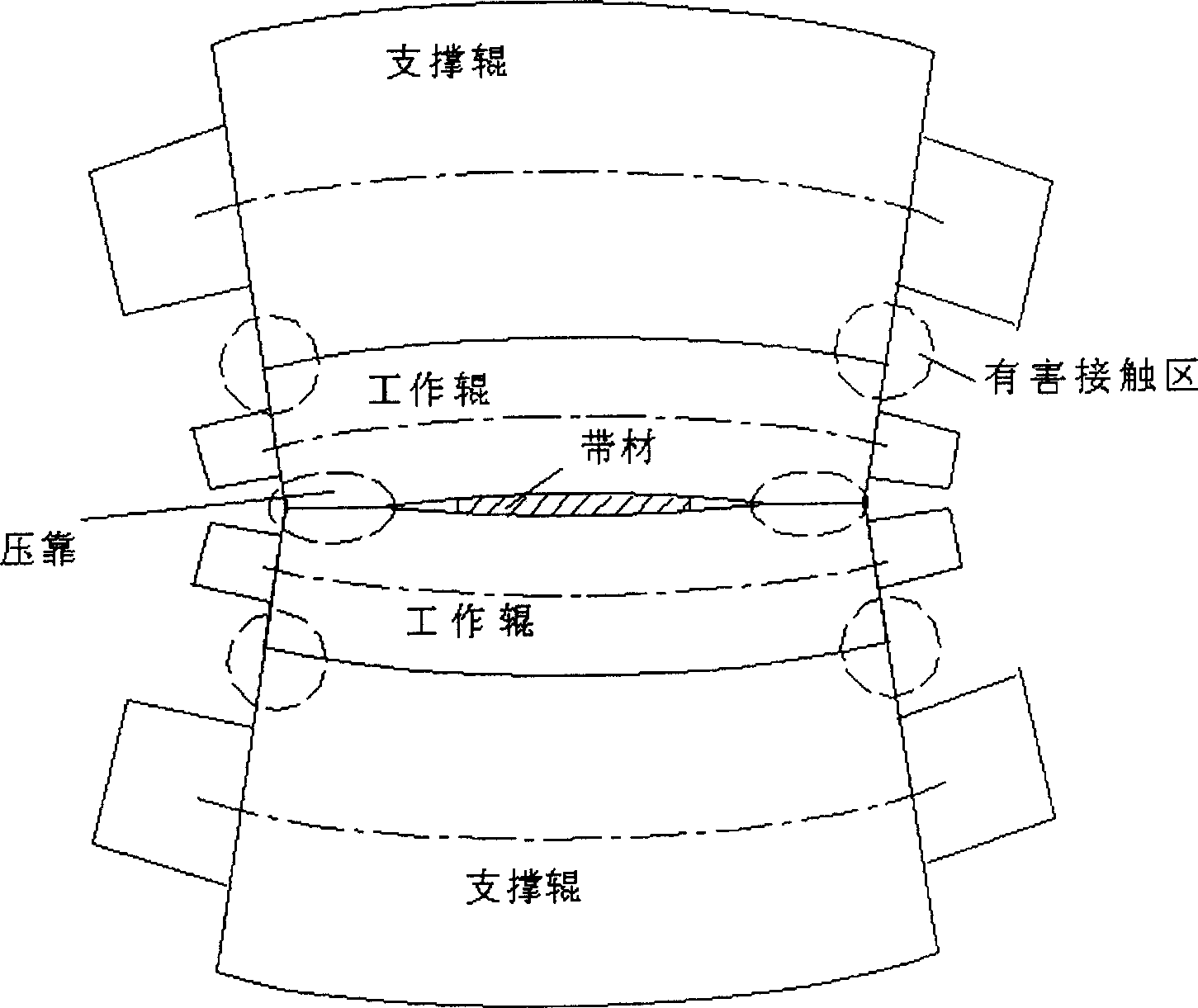
A technology of flat rolling and curve design, applied in computing, special data processing applications, instruments, etc.

Inactive Publication Date: 2006-09-06
YANSHAN UNIV
View PDF0 Cites 19 Cited by
  • Summary
  • Abstract
  • Description
  • Claims
  • Application Information

AI Technical Summary

Problems solved by technology

[0003] In order to control the impact of pressure and eliminate the harmful contact area between the rolls, in the past, people generally only considered the plate shape and roll consumption in the roll profile design of the skin pass mill. For example, Baosteel 18003#CGL published by Bai Zhenhua, Gu Tingquan, and Wu Anmin Research on roll profile technology of hot-dip galvanizing skin pass mill, "China Mechanical Engineering" 2006, 17(1); 33-35; Bai Zhenhua, Lian Jiachuang, Liu Feng and Wang Jianqiang published roll profile of Baosteel 2050 hot rolling mill Research on optimization technology "Steel" 2002, 37(9); 35-38; the research objects of these disclosed technologies are mainly rolling ordinary strips, but no thin and narrow material group has been found as the research object, while ensuring the mechanical properties of the product The roll shape design method with the shape index can be found in the literature

Method used


Image

  • Roller type curve design method in thin narrow material smoothing and rolling process
  • Roller type curve design method in thin narrow material smoothing and rolling process
  • Roller type curve design method in thin narrow material smoothing and rolling process

Examples


Embodiment 1

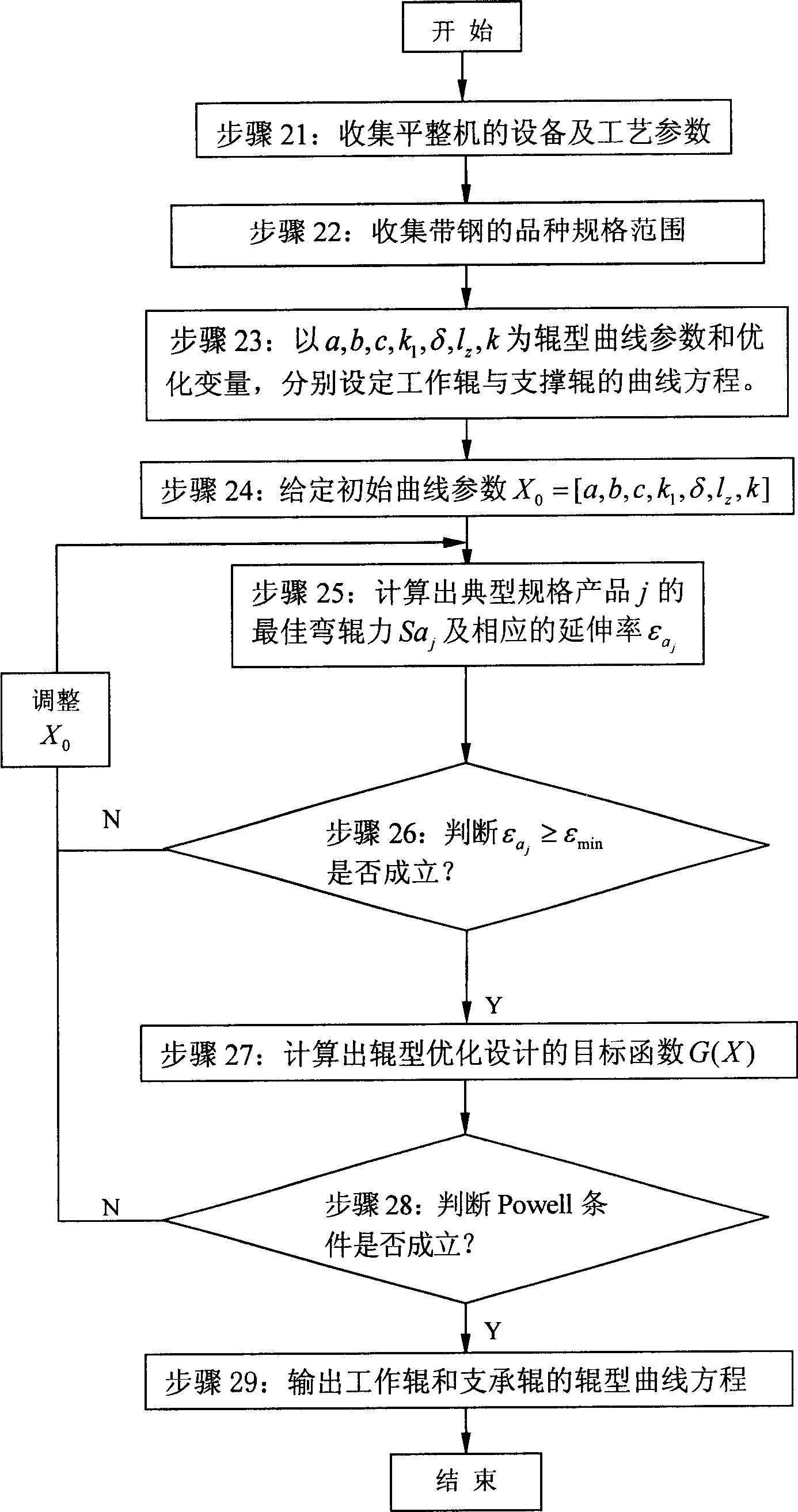
[0057] Provided below adopt the method optimization design of the present invention to design the work roll and back-up roll profile curve parameter solution process when certain common four-roller skin pass mill rolls thin and narrow material, as figure 2 shown.

[0058] First, in step 21, the equipment and process parameters of the skin pass mill are collected: work roll body length L w =1300mm, working roll diameter D w =φ440 / 480mm, back-up roll body length L b =1300mm, back-up roll diameter D b =φ1100 / 1200mm, the distance between the drive side of the backup roller and the center of the screw on the working side is l 1 = 2.32m, positive and negative bending rolls of working rolls, center distance between drive side and working side bending roll hydraulic cylinder l 2 =2.32m. The maximum bending force is ±60t, the maximum rolling pressure is 700t, and the maximum rolling speed is 1000m / min.

[0059] Subsequently, in step 22, the variety specification range of strip s...

Embodiment 2

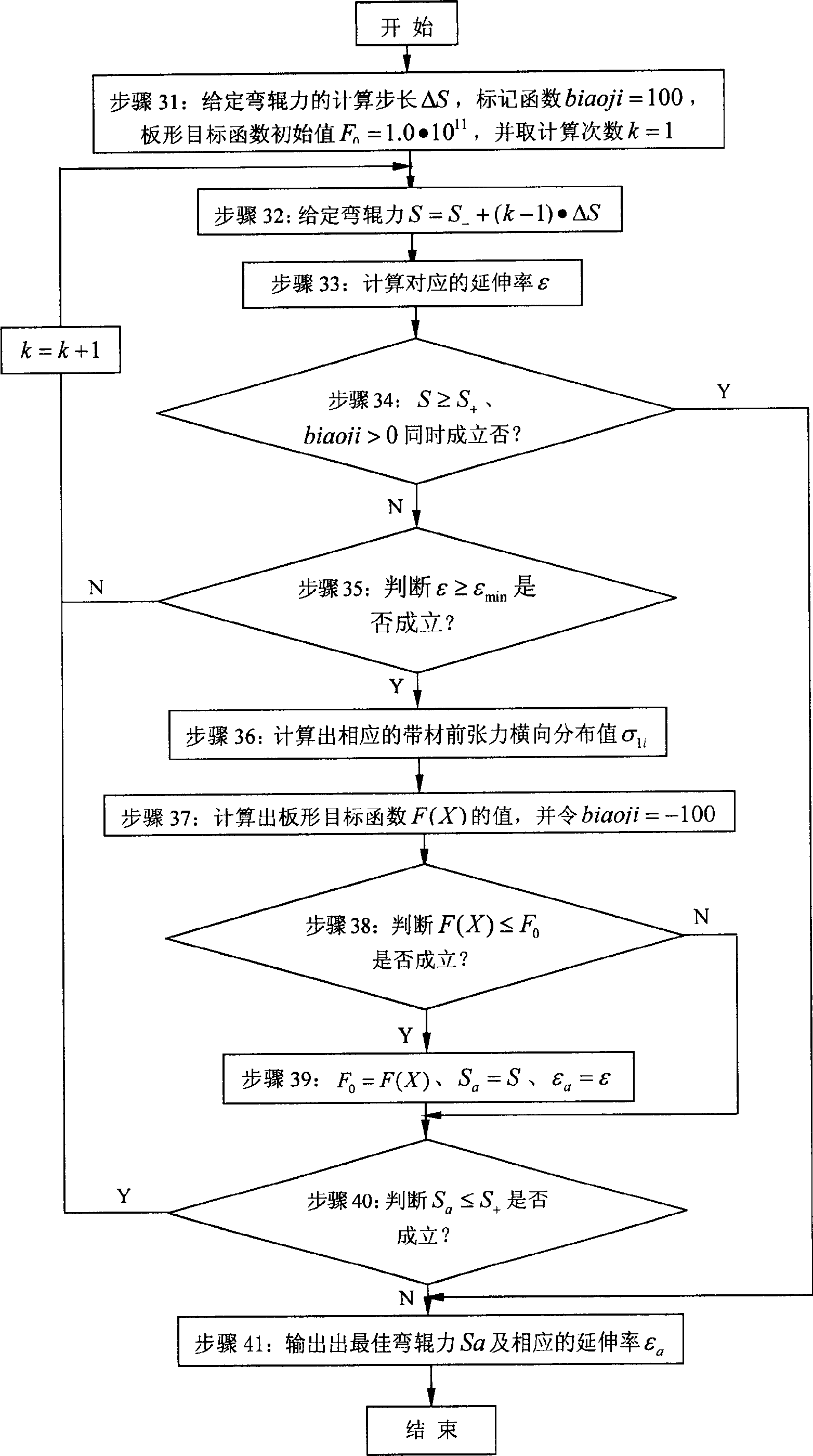
[0075] The calculation process of the optimal roll bending force when adopting the method of the present invention to solve a certain common four-roller skin pass mill rolling typical specification thin narrow material is given below, as image 3 shown.

[0076] The equipment and process parameters of the related tempering machine are: work roll body length L w =1300mm, working roll diameter D w =φ440 / 480mm, back-up roll body length L b =1300mm, back-up roll diameter D b =φ1100 / 1200mm, the distance between the drive side of the backup roller and the center of the screw on the working side is l 1 = 2.32m, positive and negative bending rolls of working rolls, center distance between drive side and working side bending roll hydraulic cylinder l 2 =2.32m. The maximum bending force is ±60t, the maximum rolling pressure is 700t, and the maximum rolling speed is 1000m / min.

[0077] Typical specifications of thin and narrow material width 800mm, thickness 0.15mm, yield strength ...


PUM

PropertyMeasurementUnit
Widthaaaaaaaaaa
Thicknessaaaaaaaaaa
Yield strengthaaaaaaaaaa

Abstract

The provided method comprises: (a) collecting the parameters on machine and technique; (b) collecting the variety and standard range of strip steel; (c) setting the curve equation for work roller and support roller; (d) optimizing the curve parameters; (e) substituting the parameters into former equations to obtain the optimal equations. This invention ensures product performance index, and can be also used to the condition with broad-thick material without pressing.

Description

technical field [0001] The invention relates to a skin pass design technology, in particular to a method for optimizing the profile curves of work rolls and back-up rolls when a common four-roll skin pass mill rolls thin and narrow materials. Background technique [0002] In production practice, it is found that when the ordinary four-roll skin pass mill rolls thin and narrow materials, the work rolls will contact and flatten the so-called pressing phenomenon outside the width of the plate, so that only a part of the set rolling pressure is used for metal deformation. Other parts are consumed in the flattening of the roll ends of the work rolls, resulting in a relatively small actual elongation, and the mechanical properties of the product cannot meet the user's requirements. Moreover, after the pressing occurs, as the rolling pressure increases, the proportion of its consumption in the roll end flattening of the work rolls also increases. When the rolling pressure increase...

Claims


Application Information

Patent Timeline
IPC IPC(8): G06F17/50
Inventor 白振华
Owner YANSHAN UNIV
Learn More