
Method for monitoring oxide layer deposition

A technology of oxide layer and silicon oxide layer, applied in semiconductor/solid-state device testing/measurement, electrical components, semiconductor/solid-state device manufacturing, etc., can solve problems such as complicated manufacturing process and inability to reflect the electrical thickness of oxide layer The effect of complex process

Inactive Publication Date: 2006-08-30
MACRONIX INT CO LTD
View PDF0 Cites 10 Cited by
  • Summary
  • Abstract
  • Description
  • Claims
  • Application Information

AI Technical Summary

Problems solved by technology

[0005] The technical problems to be solved by the present invention include the problems of process stability and output pass rate caused by the traditional method of monitoring oxide layer deposition
[0006] The technical problems to be solved by the present invention include the complicated manufacturing process caused by the traditional method of monitoring oxide layer deposition
[0007] The technical problems to be solved by the present invention include the problem that the traditional method of monitoring oxide layer deposition cannot reflect the actual electrical thickness of the oxide layer on the process wafer

Method used


Image

  • Method for monitoring oxide layer deposition
  • Method for monitoring oxide layer deposition

Examples


Embodiment Construction

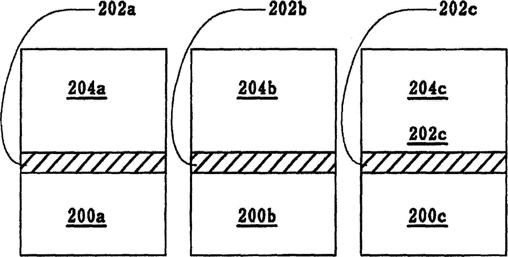
[0034] It must be noted that the structures and elements described below do not include complete structures and elements. The present invention can be implemented by various techniques and elements, and only the structures of elements required for understanding the invention are mentioned here. The following will be described in detail according to the accompanying drawings of the present invention. It must be noted that the illustrations are in a very simplified format and are not drawn to scale.

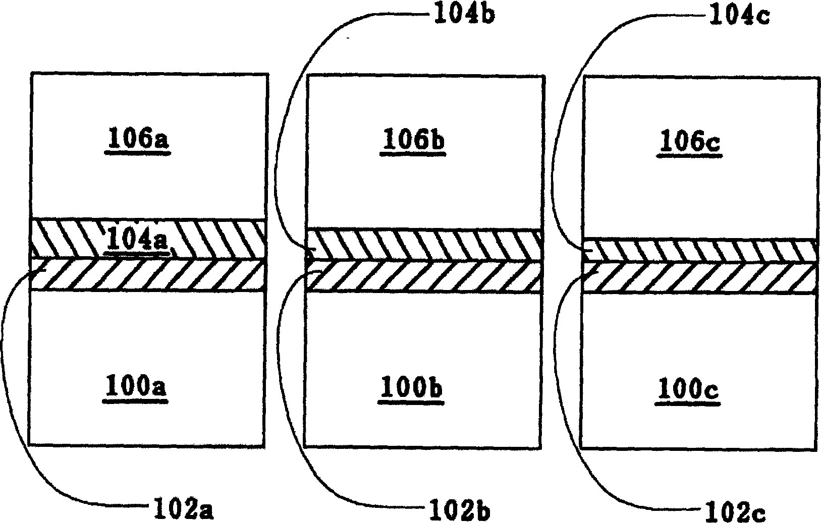
[0035] Such as figure 1 As shown and described in the prior art of the present invention, the native oxide layer on the blank wafer at the top of the furnace tube grows faster than the native oxide layer on the blank wafer at the bottom of the furnace tube, so it is deposited on the blank wafer at the bottom of the furnace tube. The native oxide layer will have a thicker oxide layer than would be deposited on the blank wafer at the top of the furnace tube.

[0036] In the proces...


PUM


Abstract

The invention discloses a method for monitoring oxide layer deposition, substituting a blank silicon wafer for a silicon wafer with silicon nitride layer to monitor deposition growth of the oxide layer in a furnace pipe, and comprising the following steps of: firstly providing a testing silicon wafer with silicon nitride layer and a manufacturing process wafer, successively carrying them together into a furnace pipe to deposit silicon oxide layers on them and controlling the thicknesses of the silicon oxide layers to make the thicknesses of the silicon oxide layers on them be about the same and measuring the thicknesses of the silicon oxide layers.

Description

technical field [0001] The invention relates to a method for monitoring the deposition of an oxide layer, in particular to a method for monitoring the deposition of a high temperature oxide layer in a vertical high temperature oxidation furnace (Vertical HTO Furnace). Background technique [0002] Oxide deposition processes currently performed in vertical furnaces have several inherent challenges that must be resolved. For example, in the oxide deposition process of the silicon oxide layer in the oxide-nitride-oxide layer (Oxide-Nitride-Oxide Stack Layer, ONO) of the semiconductor device, the oxide formed on the silicon wafer- The electrical thickness of the nitride-oxide layer varies depending on the position of the wafer in the vertical furnace tube, which is caused by the characteristics of the vertical furnace tube itself. More specifically, the variation in the electrical thickness of the oxide-nitride-oxide layer is caused by the loading of the wafer causing the tempe...

Claims


Application Information

Patent Timeline
Patent Type & Authority Applications(China)
IPC IPC(8): H01L21/66H01L21/316
Inventor 邱茂展周美君王庆堂苏耿晖
Owner MACRONIX INT CO LTD
Learn More