
Out-of-step detection method and device of synchronous motor

A technology of a synchronous motor and a detection method, which is applied to measurement devices, motor generator tests, emergency protection circuit devices, etc., can solve problems such as unfavorable promotion, damage to the compressor winding excitation device, and the compressor cannot work normally, and achieves a solution to the problem. Process complex effects

Active Publication Date: 2017-02-01
GUANGZHOU SHIYUAN ELECTRONICS CO LTD
View PDF3 Cites 9 Cited by
  • Summary
  • Abstract
  • Description
  • Claims
  • Application Information

AI Technical Summary

Problems solved by technology

During the operation of a synchronous motor, due to heavy load, improper drive control, external interference, etc., it is easy to cause the rotation speed of the rotor and the rotation speed of the stator magnetic field to be out of sync, resulting in a synchronous motor out of step phenomenon
If the synchronous motor is out of step for a long time, the compressor winding or excitation device will be damaged, resulting in the compressor not working properly
The existing methods for detecting synchronous motor out-of-step mainly include current sampling method and voltage sampling method, which cannot directly judge the out-of-step of synchronous motor through the difference between the rotation speed of the rotor and stator magnetic fields, and different types of synchronous motors need to adopt different schemes , the process is complicated, which is not conducive to the promotion

Method used


Image

  • Out-of-step detection method and device of synchronous motor
  • Out-of-step detection method and device of synchronous motor
  • Out-of-step detection method and device of synchronous motor

Examples


Embodiment Construction

[0027] The technical solutions in the embodiments of the present invention will be clearly and completely described below in conjunction with the accompanying drawings in the embodiments of the present invention. Obviously, the described embodiments are only a part of the embodiments of the present invention, rather than all the embodiments. Based on the embodiments of the present invention, all other embodiments obtained by those of ordinary skill in the art without creative work shall fall within the protection scope of the present invention.

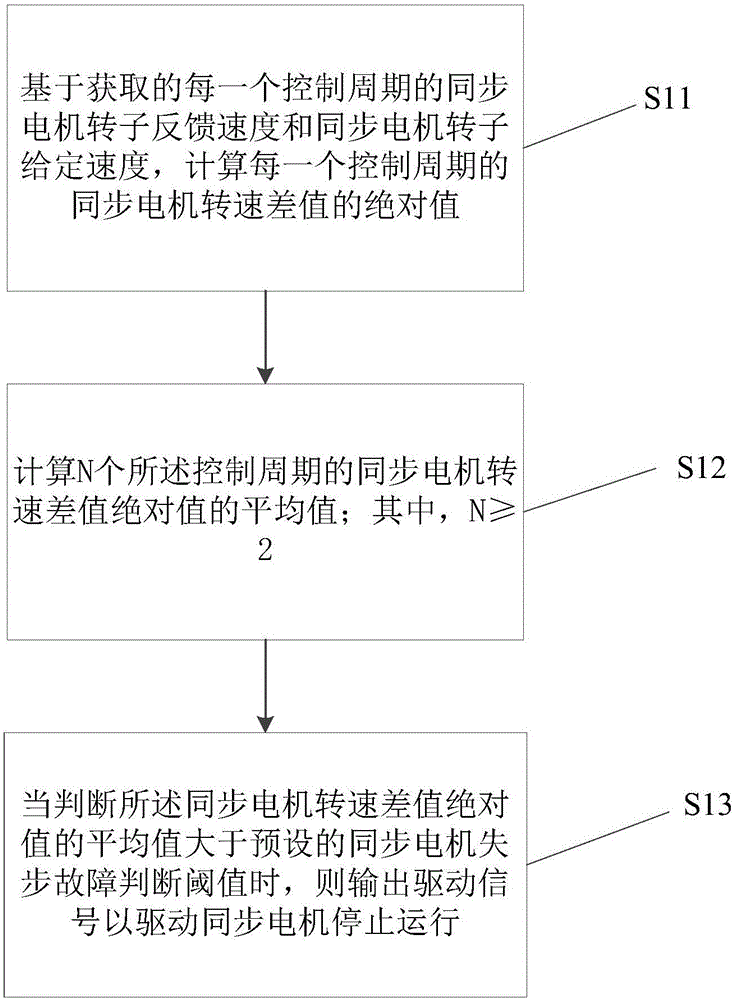
[0028] See figure 1 , Is a flowchart of a synchronous motor out-of-step detection method provided by Embodiment 1 of the present invention. figure 1 The shown method for detecting out-of-step of a synchronous motor includes the following steps:

[0029] S11. Calculate the absolute value of the synchronous motor speed difference in each control period based on the acquired synchronous motor rotor feedback speed and the synchronous motor roto...


PUM


Abstract

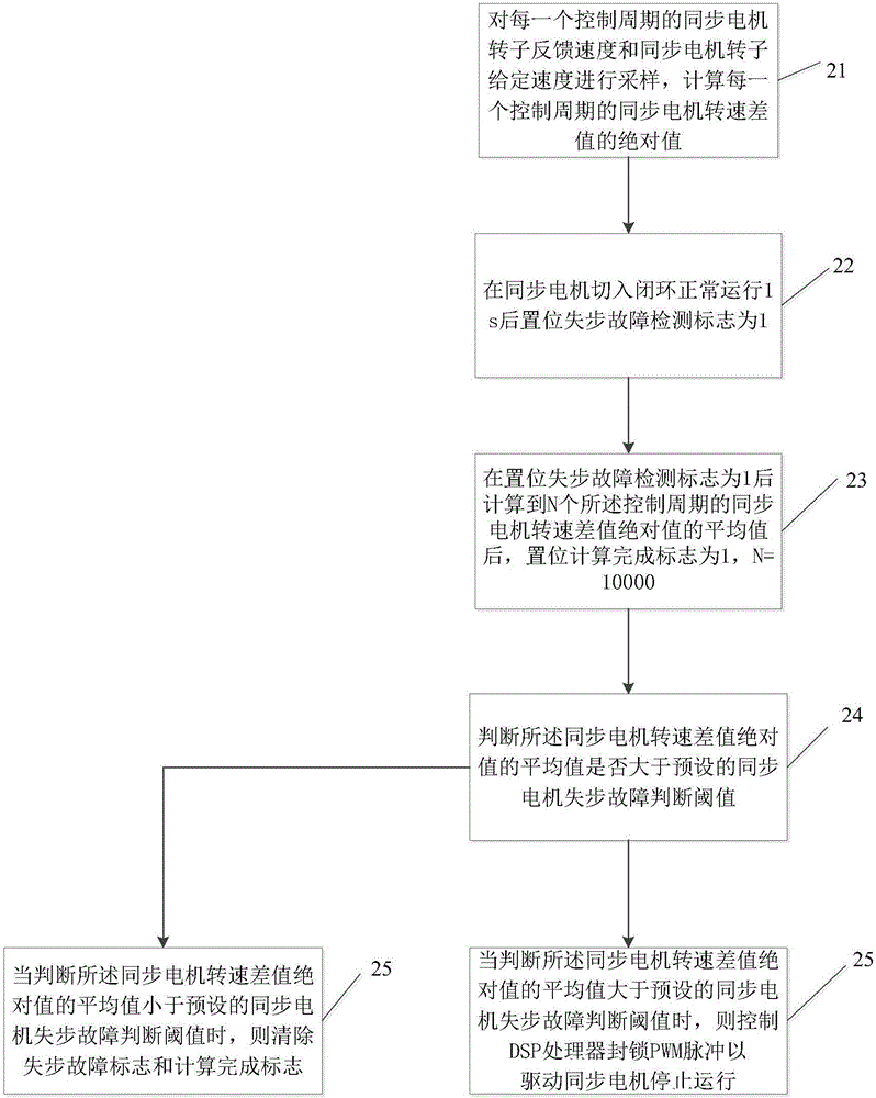
The embodiment of the invention discloses an out-of-step detection method of a synchronous motor. The out-of-step detection method comprises the steps of calculating an absolute value of a rotational speed difference value of the synchronous motor in each control period according to a feedback speed of a rotor of the synchronous motor and a given speed of the rotor of the synchronous motor, which are acquired in each control period; calculating an average value of absolute values of rotational speed difference values of the synchronous motor in N control periods, wherein N is more than or equal to 2; and outputting a driving signal to drive the synchronous motor to stop running when the average value of the absolute values of the rotational speed difference values of the synchronous motor is judged to be larger than a preset out-of-step fault judgment threshold value of the synchronous motor. According to the out-of-step detection method of the synchronous motor, provided by the invention, an out-of-step fault of the synchronous motor is detected by judging whether the average value of the absolute values of the rotational speed difference values of the synchronous motor is larger than the preset out-of-step fault judgment threshold value or not, and the out-of-step detection method is direct, simple, rapid and effective and is applicable to different types of synchronous motors.

Description

Technical field [0001] The invention relates to the field of motor detection, in particular to a synchronous motor out-of-step detection method and a synchronous motor out-of-step detection device. Background technique [0002] Synchronous motors are widely used in compressors, blowers, ball mills and other fields with high efficiency, small size and low noise. During the operation of the synchronous motor, due to excessive load, improper drive control, external interference, etc., it is easy to cause the rotor rotation speed and the stator magnetic field rotation speed to be out of sync, causing the synchronous motor to lose synchronization. If the synchronous motor stays out of step for a long time, it will damage the compressor winding or the excitation device and cause the compressor to fail to work normally. The existing methods for detecting synchronous motor out-of-step mainly include current sampling method and voltage sampling method. It is not possible to directly judg...

Claims


Application Information

Patent Timeline
IPC IPC(8): H02H7/08G01R31/34
CPCG01R31/343H02H7/0805
Inventor 邓焕明
Owner GUANGZHOU SHIYUAN ELECTRONICS CO LTD
Learn More