Kreuzkopfmotor

A cross-head, engine technology, used in engine components, engine cooling, machine/engine, etc., can solve the problems of difficult manufacturing, shortened service life, large size, etc., to achieve convenient manufacturing, reliable placement, good stress The effect of distribution

Inactive Publication Date: 2006-08-30
MAN DIESEL & TURBO FILIAL AF MAN DIESEL & TURBO SE TYSKLAND
View PDF0 Cites 0 Cited by
  • Summary
  • Abstract
  • Description
  • Claims
  • Application Information

AI Technical Summary

Problems solved by technology

This makes it more difficult to manufacture
Another disadvantage is that the bore leading away from the lower end of the outer flow channel extends relatively far into the lower region of the piston rod through the flange height of the piston rod
In operation, as shown in experiments, this leads to poor stress distribution and consequently known arrangements with a shorter service life or with larger dimensions in the outermost

Method used


Image

  • Kreuzkopfmotor
  • Kreuzkopfmotor
  • Kreuzkopfmotor

Examples


Embodiment Construction

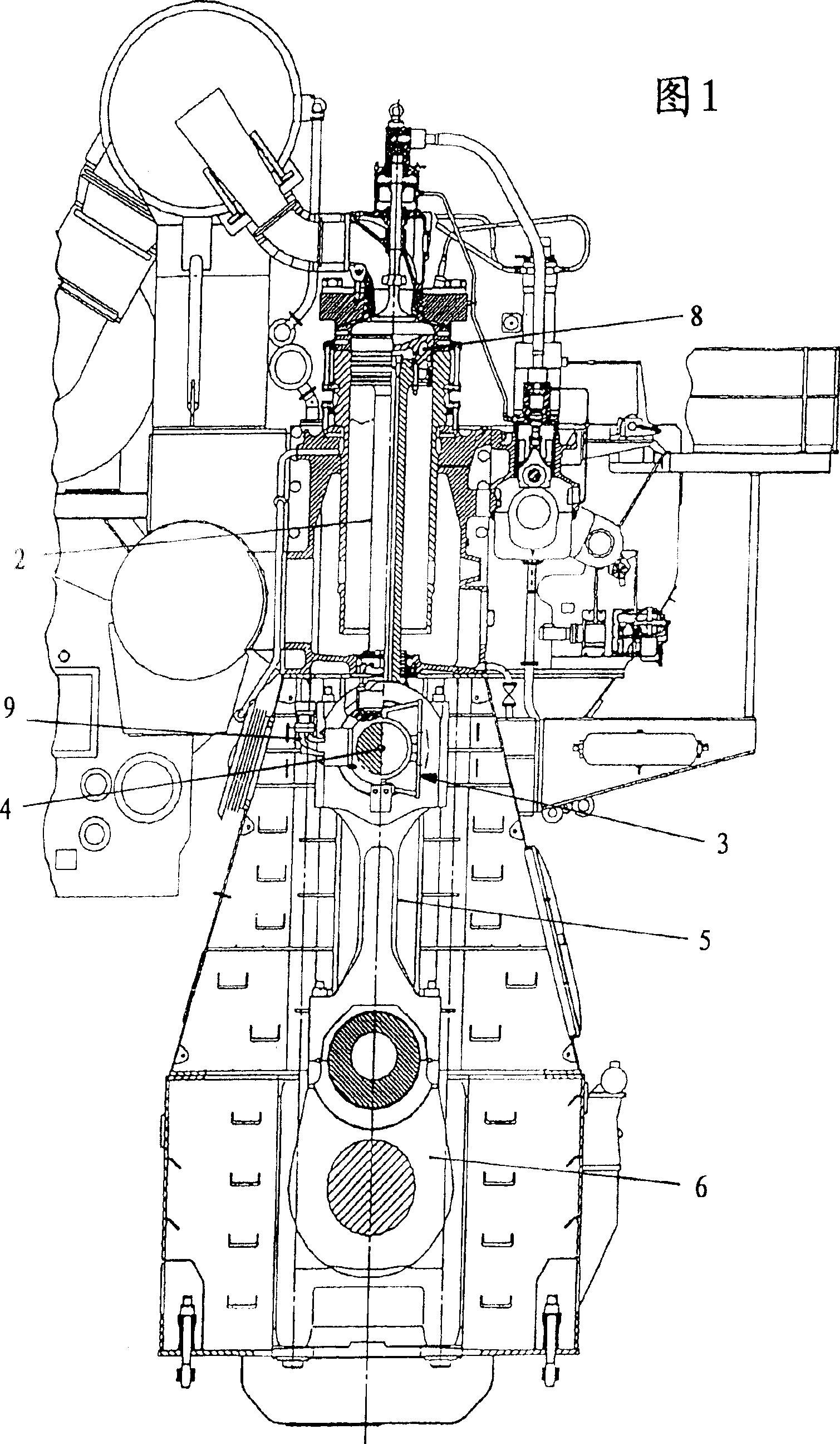
[0020] For example, the basic structure and mode of operation of two-stroke large diesel engines suitable for marine power or the like are known per se. As shown in Figure 1, engines of this type are often designed as crosshead engines. Each piston 1 is connected to a crosshead 3 via a piston rod 2 . The crosshead 3 actually forms a slide which is guided in the direction of the machine frame parallel to the piston pin. The crosshead 3 comprises a crosshead journal 4 arranged perpendicular to the axis of the piston rod 2, in which the piston rod 2 is fixed and on which a connecting rod 5 is supported, which The rod 5 connects the crosshead 3 to a crankshaft 6 which is arranged in the lower region of the engine block.

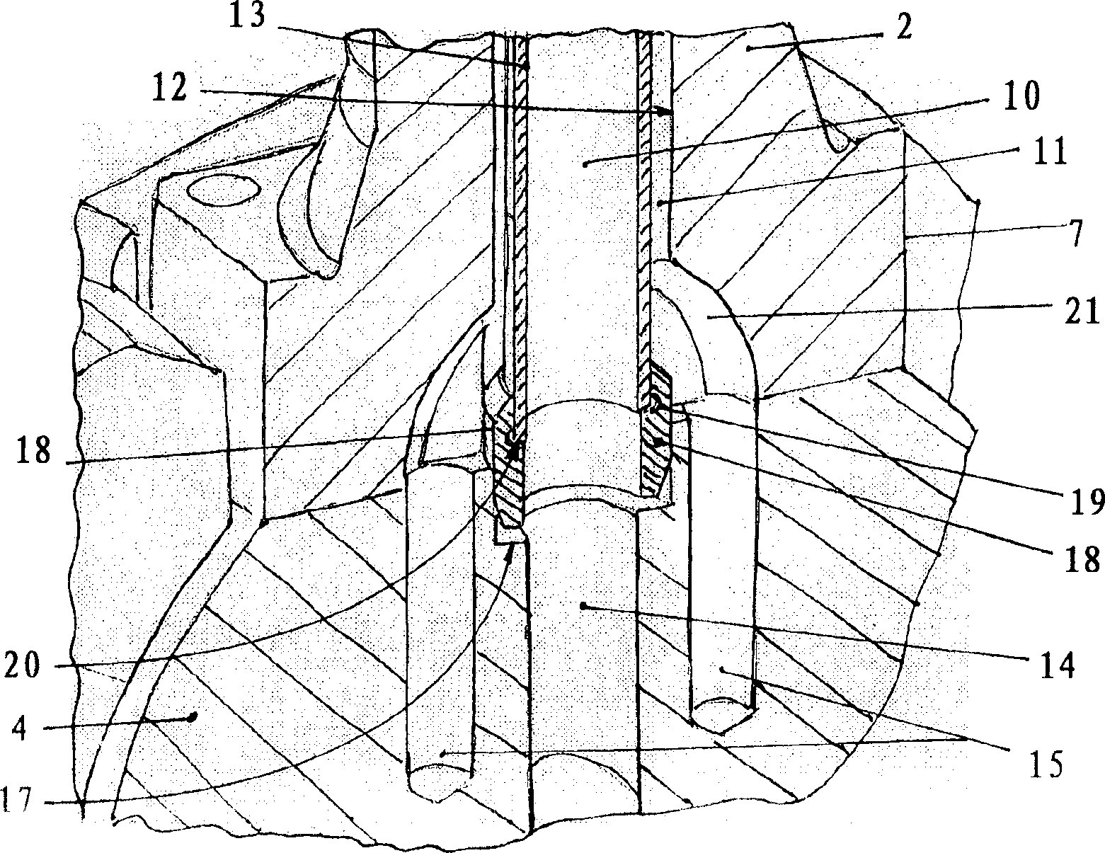
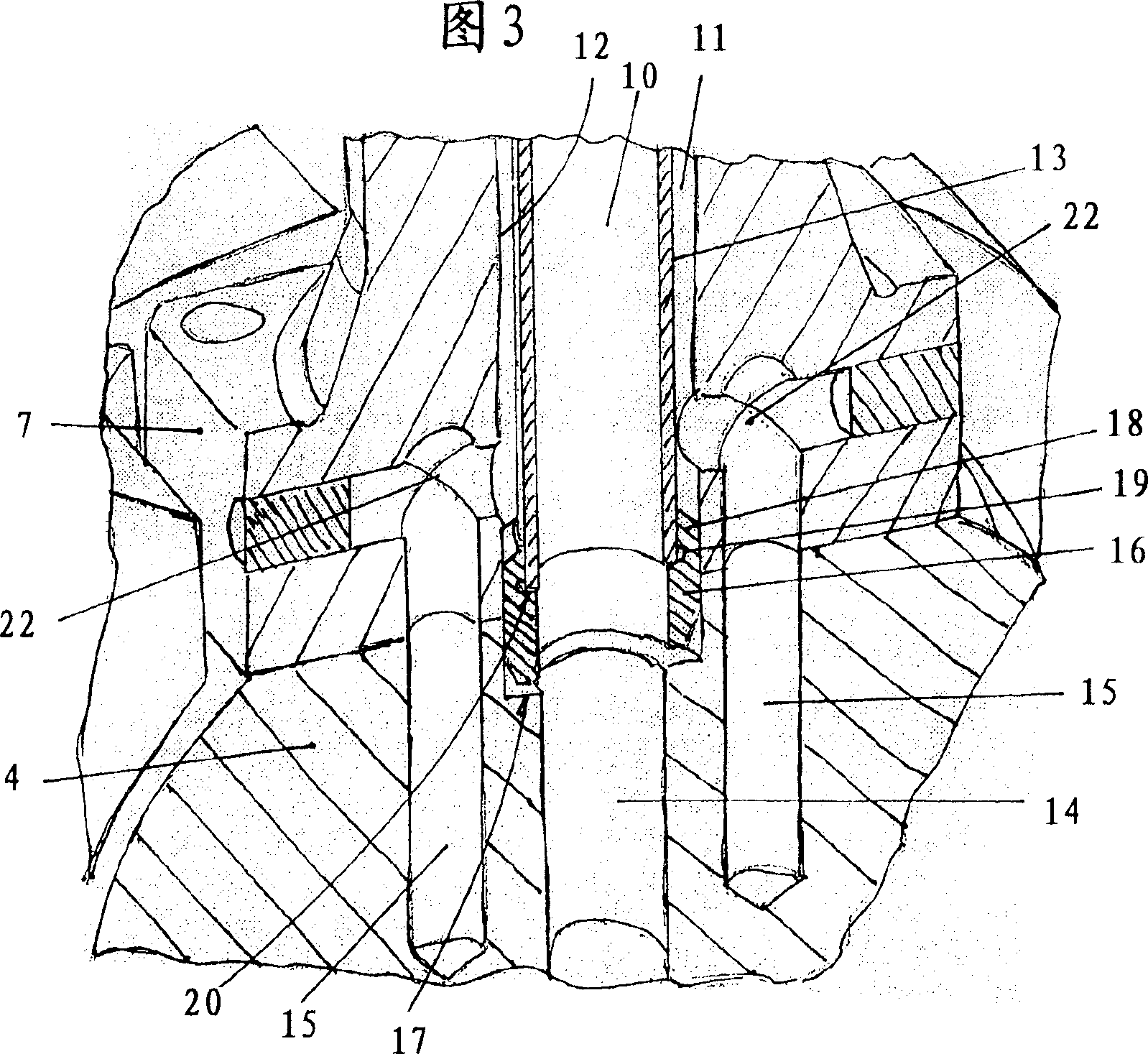
[0021] as other figure 2 As shown in -4, the piston rod 2 is provided with a flange 7 at the lower end, which abuts against a matching bearing surface of the crosshead journal 4 with its lower end surface. The flange 7 has holes for the passage of bolts, by ...


PUM


Abstract

Cross-head engine e.g. two-stroke large diesel engine has through recess (12) of piston rod (2) which is formed as smooth through-bore below their upper end area and input pipe (13) with its lower end area is placed within through recess, which is meshed in central sleeve whose outer diameter is larger compared to outer diameter of input pipe, which corresponds to diameter of through-bore. An Independent claim is also included for the device.

Description

technical field [0001] The invention relates to a crosshead engine, especially a large two-stroke diesel engine, which has at least one piston connected to a crosshead journal through a piston rod, and the piston is connected to a crosshead journal through a A cooling fluid is supplied by a channel system in which the piston rod is provided with a through hole, and a centering sleeve protruding from a radial hole concentric with the crosshead journal is fitted into the lower end of the through hole. area, while the area of ​​the through-hole located above this is divided into flow channels on the side of a crosshead journal via a cannula whose lower end is embedded and has a smaller outer diameter compared to the diameter of the through-hole. There is an inner flow channel and an outer flow channel that are connected to the coolant. Background technique [0002] A known arrangement of such engines is in the form of notches from Image 6 can be clearly seen in . The through...

Claims


Application Information

Patent Timeline
IPC IPC(8): F02B75/32F01P3/06F16J7/00
CPCF01P3/10F01P11/04B28B7/0014B28B21/84
Inventor J·拉思曼
Owner MAN DIESEL & TURBO FILIAL AF MAN DIESEL & TURBO SE TYSKLAND
Why Eureka
Try Eureka