
Film forming device, film forming method, method and apparatus for fabricating self-emission device

A self-luminous, film-forming technology, applied in the field of manufacturing devices, can solve problems such as electrode short circuit, component degradation, and adverse effects

Inactive Publication Date: 2006-08-30
TOHOKU PIONEER CORP
View PDF0 Cites 1 Cited by
  • Summary
  • Abstract
  • Description
  • Claims
  • Application Information

AI Technical Summary

Problems solved by technology

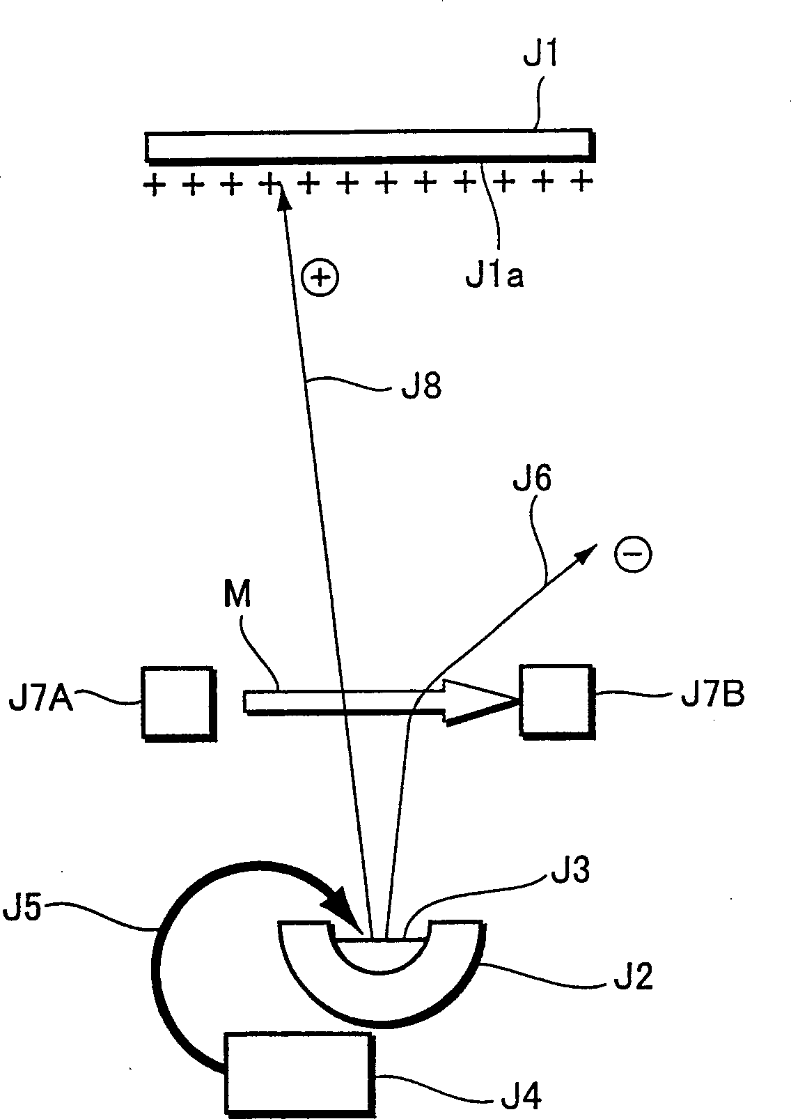
[0009] In this way, if positive ions are accumulated on the formed metal thin film, there will be a problem that the static electricity formed by its charging will have a bad influence on the surroundings, and the metal that forms the self-luminous element by such electron beam evaporation will In the case of an electrode, a large electric field is applied to the self-luminous element due to the static electricity formed by the accumulation of cations. For example, when an organic EL element is formed by sandwiching an organic layer between a pair of electrodes, due to the Positive electricity generated on the electrodes, and a large electric field is applied between the organic layers, and strong stress is generated due to the electric field, resulting in problems such as component degradation and short circuits between electrodes.

Method used


Image

  • Film forming device, film forming method, method and apparatus for fabricating self-emission device
  • Film forming device, film forming method, method and apparatus for fabricating self-emission device

Examples


Embodiment Construction

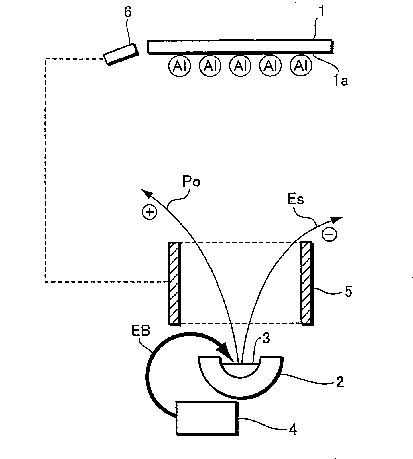
[0026] Embodiments of the present invention will be described below with reference to the drawings. figure 2 It is an explanatory diagram for explaining a film forming method and a film forming apparatus according to an embodiment of the present invention.

[0027] This film-forming device forms a metal thin film such as Al on the film-forming surface 1a of the substrate 1 by electron beam evaporation, and has the function of irradiating the metal material 3 accommodated in the film-forming source 2 with an electron beam generator (electron gun). The electron beam irradiation unit 4 of the electron beam EB melts the metal material 3 by irradiation of the electron beam, and the generated metal vapor is vapor-deposited on the film-forming surface 1a of the substrate 1 to form a metal thin film, and also has a charge trajectory changing unit 5. It changes the trajectory of electrons ES (secondary electrons or bounced electrons) and positive ions Po generated by irradiating electr...


PUM


Abstract

The invention is intended to avoid a metal thin film from being in an electostatically charged state by preventing secondary electrons or the like from reaching to a surface to be film-deposited and preventing cations from reaching to the surface to be film-deposited in the deposition of the metal thin film by means of an electronic beam vapor deposition. The film deposition apparatus for depositing the metal thin film of Al or the like by the electronic beam vapor deposition on the surface 1a of a substrate 1 has an electronic beam irradiation means 4 to irradiate a metal material 3 stored in a film deposition source 2 with electronic beams EB from an electronic beam generator (an electron gun), and a charge track changing means 5 to change the advancing tracks of electrons Es and cations Po generated by irradiation of electron beams on the film deposition source 2 so as not to reach the surface 1a.

Description

technical field [0001] The present invention relates to a film-forming method and a film-forming device, and a method and device for producing a self-luminous element. Background technique [0002] An electron beam vapor deposition method is known as one of methods for forming a film of a metal material on a film-forming surface. Compared with general heating evaporation, this electron beam evaporation method can obtain a higher film formation rate, so it is used in the formation of metal electrode films for self-luminous elements such as organic EL (Organic Electro Luminescence, organic electroluminescence) elements. , can shorten the manufacturing time. [0003] FIG. 1 is an explanatory diagram for explaining the formation of a metal thin film by conventional electron beam evaporation. According to this figure, the substrate J1 is arranged in a vacuum film-forming chamber, and the metal material J3 accommodated in the film-forming source (crucible) J2 is irradiated with ...

Claims


Application Information

Patent Timeline
IPC IPC(8): C23C14/30
CPCC23C14/12C23C14/24H10K71/164H10K71/00
Inventor 丹博树
Owner TOHOKU PIONEER CORP
Learn More