
Fuel supply device with a pressure accumulator tube closed by accumulator cover

A technology of fuel supply and pressure accumulator, which is applied to fuel injection devices with fuel storage, fuel injection devices, charging systems, etc., which can solve the problems of assembling and disassembling functional units, and achieve improved accessibility and optimization Component manufacturing and the effect of manufacturing plan improvement

Active Publication Date: 2010-06-09
MAN ENERGY SOLUTIONS SA
View PDF5 Cites 0 Cited by
  • Summary
  • Abstract
  • Description
  • Claims
  • Application Information

AI Technical Summary

Problems solved by technology

Overall, assembly and disassembly of the functional units of the conventional pressure accumulator cover in the high-pressure connection is relatively complex

Method used


Image

  • Fuel supply device with a pressure accumulator tube closed by accumulator cover
  • Fuel supply device with a pressure accumulator tube closed by accumulator cover
  • Fuel supply device with a pressure accumulator tube closed by accumulator cover

Examples


Embodiment Construction

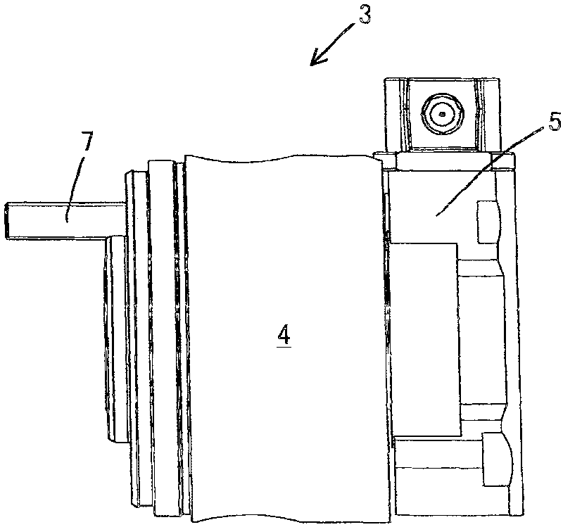
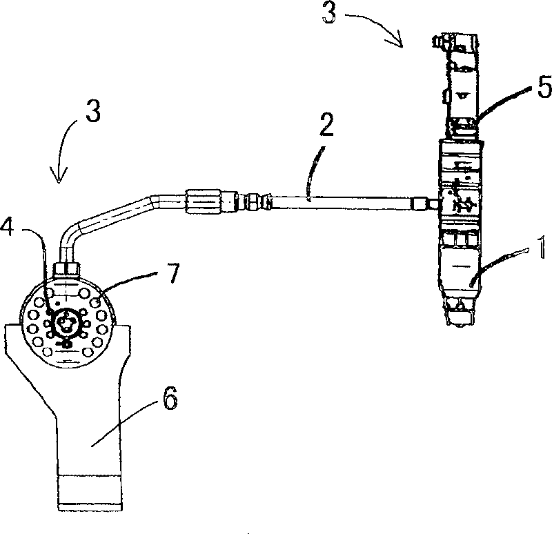
[0026] Pressure accumulator units are known to consist of pipe-like components with or without inserts, which by means of press Figures 1 to 4 The pressure accumulator covers are each sealed at the end faces and are arranged approximately at the level of the cylinder head along the internal combustion engine (not shown).

[0027] Each pressure accumulator unit is connected by means of at least one pressure line 2 to at least one injector 1 , which is usually electrically controlled.

[0028] Preferably, one pressure accumulator unit is provided for each of the two cylinders to be actuated. In the case of an odd number of cylinders, a freely positionable pressure accumulator unit operates only one cylinder. Depending on the engine type and application, the respective interconnected pressure accumulator units are charged by two to six high-pressure pumps.

[0029] As stated at the outset, the fuel enters the pressure accumulator cover 3 from the respective pressure accumulato...


PUM


Abstract

The invention relates to a fuel supply device in the form of a common rail injection system, which comprises at least one accumulating chamber in an accumulator unit, which can be sealed by at least one end surface by an accumulator cover, wherein all functional units are integrated in the accumulator cover in consideration of the supply and the guide of fuel. In order to be accessible to each functional unit and keep the advantages that the attenuation of the amplitude pressure applied on the functional units of the accumulator cover, specifically a two-position three-port valve and a pressure pipe, the invention provides that the accumulator cover consists of two modules in a form of a sealing element and a control unit, so that the sealing element is hermetically connected with the accumulator unit, and the control unit can be located optionally in the pressure pipe between the sealing element and a fuel injector for supplying fuel.

Description

technical field [0001] The invention relates to a fuel supply device in the form of a common rail injection system for supplying fuel injectors of cylinders of an internal combustion engine via a pressure line, said fuel supply device having at least one The accumulator chamber, the accumulator unit, can be closed at least on one end side by means of an accumulator cover, wherein all functional units are integrated in the accumulator cover with regard to fuel supply and guidance. Background technique [0002] From DE 101 57 135 A1, for example, such a fuel supply device is known, which has the following characteristics, that is, the fuel supply device is used to supply fuel to the fuel injectors of the cylinders of the internal combustion engine via the pressure line, said fuel supply device has At least one pressure accumulator chamber in a pressure accumulator unit which can be closed at least on one end face by means of a pressure accumulator cover. [0003] It has alrea...

Claims


Application Information

Patent Timeline
Patent Type & Authority Patents(China)
IPC IPC(8): F02M45/04F02M55/02F02M63/00F02M63/02F02M
CPCF02M63/0031F02M63/0043F02M55/025F02M63/0045F02M63/0225F02M2200/40F02M55/02F02M63/00
Inventor C·格拉斯珀伊恩特纳L·迈尔C·福格尔W·瓦尔克纳H·亚尔钦
Owner MAN ENERGY SOLUTIONS SA
Learn More