Eureka AIR delivers breakthrough ideas for toughest innovation challenges, trusted by R&D personnel around the world.

Down air-exhaust type oil-fume removing device

A technology for exhausting oil fume and oil fume, which is applied in the direction of oil fume removal, heating methods, household heating, etc., can solve the problems of oil fume blocking, unsatisfactory emission effect, large energy consumption, inhalation, etc., and achieves benefits to human health , Good discharge effect, easy to use

Inactive Publication Date: 2006-08-09
林润泉
View PDF1 Cites 4 Cited by
  • Summary
  • Abstract
  • Description
  • Claims
  • Application Information

AI Technical Summary

Problems solved by technology

[0002] At present, the oil fume exhaust devices commonly used by people are mostly upper-hanging and exhaust-type range hoods. The distance between them is relatively large, and the oily fume is difficult to be completely collected and sucked out. The oily fume is easy to spread into the kitchen space and be inhaled by people, thereby polluting the environment and affecting human health.
Therefore, its shortcoming is that oil fume cannot be discharged completely, which pollutes the environment and is not conducive to human health.
Chinese invention patent CN1325002A discloses a fluid diaphragm suction and exhaust device, which is mainly composed of a pressurized fluid outlet parallel to the diffusion surface of the smoke pollution source, a negative pressure fluid suction port, a pressurized fluid source and a negative pressure generating device. The pressure fluid blowing outlet is arc-shaped, and the diaphragm layer of the blown fluid is prone to mutual cross disturbance, and only one side is the oil fume suction and discharge port, so the oil fume is blocked and the discharge effect is not ideal, and the pressure fluid is blown out and the oil fume is blown out. Negative pressure suction and discharge of flue gas requires power consumption, which consumes a lot of energy, so its disadvantage is that it consumes a lot of energy and the effect of oil fume emission is not very ideal

Method used


Image

  • Down air-exhaust type oil-fume removing device
  • Down air-exhaust type oil-fume removing device
  • Down air-exhaust type oil-fume removing device

Examples


Embodiment 1

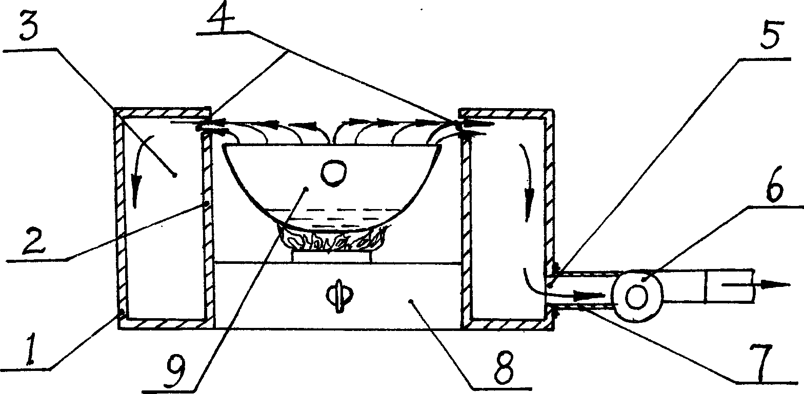
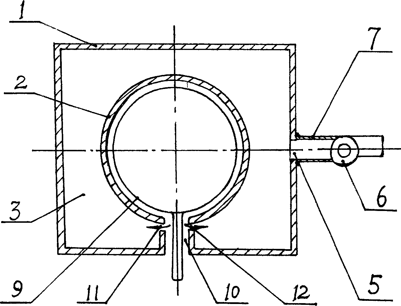
[0024] Example 1, in figure 1 The schematic diagram of the structure shown, figure 2 The schematic top view and image 3 In the schematic diagram of the partial structure shown, the present invention includes an outer casing 1 and a cylindrical cooker enclosure 2 inside it, and the outer casing 1 and the cooker enclosure 2 form a cooker enclosure with an oil fume exhaust cavity 3, Wherein, between the outer casing 1 and the annular upper edge of the cooker coaming plate 2, there are oil fume suction and discharge ports 4 distributed around the oil fume diffusion surface, and the oil fume suction and discharge ports 4 are The continuous annular suction and discharge port is located slightly higher than the position of the oil fume diffusion surface (that is, the position of the upper opening of the cooker). Fume port 5. The negative pressure source is an exhaust fan 6 , and the exhaust fan 6 is arranged on the oil fume exhaust pipe 7 communicating with the oil exhaust fume ...

Embodiment 2

[0025] In Embodiment 2, the present invention has the same structure as that described in Embodiment 1, except that an oil fume filter is added. exist Figure 4 In the schematic diagram of the partial structure shown, the present invention also includes an oil fume filter 13, which is arranged at the oil fume outlet 5 on the outer casing 1 to filter and purify the oil fume, and its material is generally Non-woven fabric, but when other materials are used, it also belongs to the protection scope of the present invention.

Embodiment 3

[0026] Embodiment 3, the present invention has the same structure as Embodiment 1 except that a deflector for oil fume discharge is added. exist Figure 5In the schematic diagram shown, the present invention also includes an arc-shaped oil fume discharge deflector 14, which is arranged at the inner cavity at the upper corner of the outer side formed by the upper cover plate and the outer shroud of the outer casing 1, and is in the direction of the above-mentioned The concave streamline shape in the upper corner direction of the outer side can reduce the diversion resistance to the inhaled oil fume, so that it can be smoothly diverted and discharged.


PUM


Abstract

Present invention relates to a lower air draft type fume exhauster. It mainly includes casing, cylindrical shaped enclosed board, fume exhausting cavity formed by above-mentioned casing and enclosed board, upper cover board, fume suction and exhausting opening distributed on fume diffusing surface circumference. It solves current exhauster low effect and high energy consumption problem, used in kitchen cooking utensils.

Description

technical field [0001] The invention relates to an oil fume exhaust device, in particular to a down-draft type oil fume exhaust device which can be used in kitchens or other sources of oil fume. Background technique [0002] At present, the oil fume exhaust devices commonly used by people are mostly upper-hanging and exhaust-type range hoods. The distance between them is large, and it is difficult for the oily fume to be completely collected and sucked out. The oily fume is easy to diffuse into the kitchen space and be inhaled by people, thereby polluting the environment and affecting human health. Therefore, its shortcoming is that oil fume cannot be completely discharged, which pollutes the environment and is not conducive to human health. Chinese invention patent CN1325002A discloses a fluid diaphragm suction and exhaust device, which is mainly composed of a pressurized fluid outlet parallel to the diffusion surface of the smoke pollution source, a negative pressure flui...

Claims


Application Information

Patent Timeline
Patent Type & Authority Applications(China)
IPC IPC(8): F24C15/20
Inventor 林润泉
Owner 林润泉
Why Eureka
Eureka Blog
Learn More