
Pneumatic tire

A technology for pneumatic tires and tires, which is applied to the reinforcement layer of pneumatic tires, special tires, tire parts, etc., can solve the problems of insufficient transmission, increased rolling resistance, and inability to fully improve the lateral spring constant and circumferential spring constant, etc. Achieve the effect of increasing lateral spring constant and circumferential spring constant, reducing rolling resistance and longitudinal spring constant, and improving handling stability

Inactive Publication Date: 2006-07-19
THE YOKOHAMA RUBBER CO LTD
View PDF2 Cites 6 Cited by
  • Summary
  • Abstract
  • Description
  • Claims
  • Application Information

AI Technical Summary

Problems solved by technology

[0005] However, in the reinforcement structure combining the bead filler and the tire side reinforcement as described above, the transmission of force between the bead filler and the tire side reinforcement is insufficient, and the lateral spring constant cannot be sufficiently improved. and the circumferential spring constant
In addition, in the case of small bead filler, the reinforcing effect of the bead portion is insufficient, and the lateral spring constant cannot be sufficiently increased.
Therefore, the handling stability is definitely not sufficient
Furthermore, if the vicinity of the belt end is reinforced, the rolling resistance will increase and the fuel efficiency will deteriorate
[0006] As described above, it is difficult to simultaneously improve various tire performances based on the reinforcement structure of the bead portion and the tire sidewall portion. In order to exert the optimum tire performance, the reinforcement structure must be sufficiently specified.

Method used


Image

  • Pneumatic tire
  • Pneumatic tire
  • Pneumatic tire

Examples


Embodiment

[0054] In a pneumatic tire of tire size 205 / 65R15, conventional examples, Examples 1 to 7, and Comparative Examples 1 to 1 were produced in which only the reinforcing structures of the tire side portion and the bead portion were different as shown in Tables 1 and 2. 10.

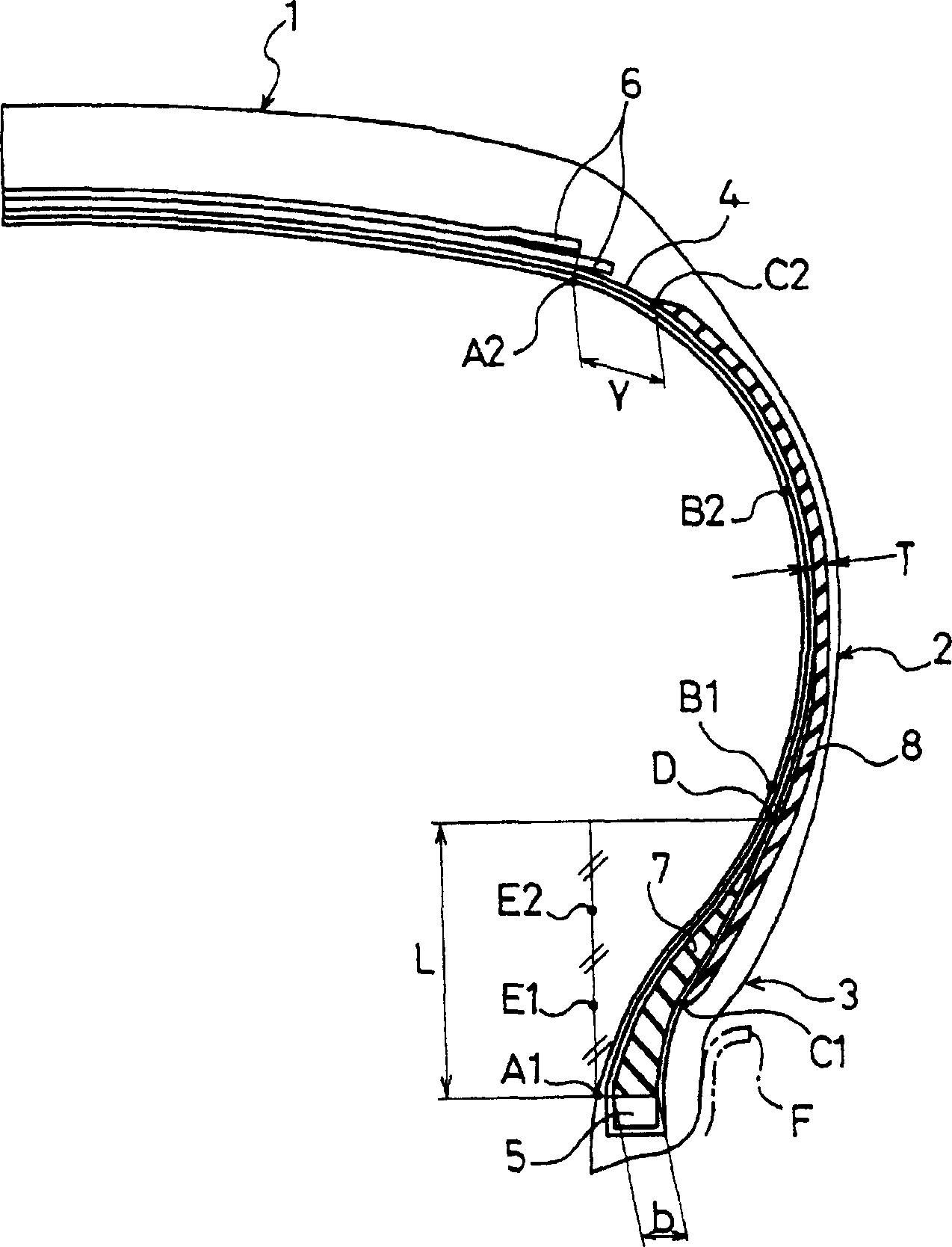
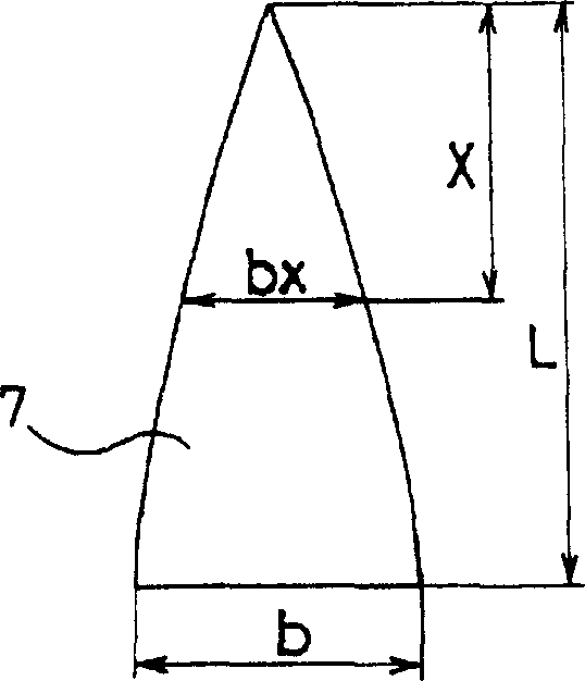
[0055] Here, in all the tires, the JIS-A hardness of the carcass rubber is set to 64, the JIS-A hardness of the tire side rubber is set to 65, and the height of point B1 (height from the upper end of the bead core) is set to is 43mm, the height of the rim bead (the height from the upper end of the bead core) is set to 15mm, the width b of the filler on the bottom edge of the bead filler is set to 8mm, and the JIS-A hardness of the bead filler is set to is 92.

[0056] For these test tires, road noise, ride comfort, handling stability, and rolling resistance were evaluated by the following methods, and the results are shown in Tables 1 and 2 together.

[0057] Road Noise:

[0058] Each experimental tire was...


PUM

PropertyMeasurementUnit
thicknessaaaaaaaaaa
hardnessaaaaaaaaaa
dielectric lossaaaaaaaaaa

Abstract

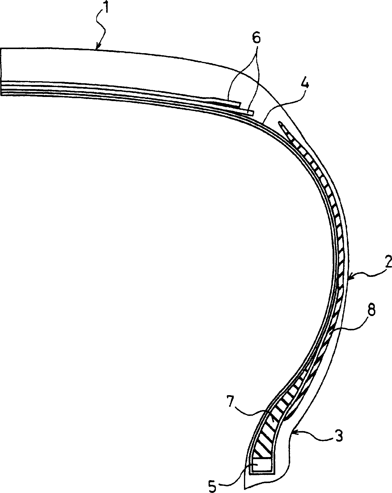
A pneumatic tire improving driving stability, road noise, riding comfort, and a fuel consumption performance in a balanced manner. The pneumatic tire includes: a bead filler made wider than a triangle formed by connecting its base and top in a cross-sectional view taken along a meridian of the tire; and a sheet-like auxiliary filler arranged from a sidewall portion to a bead portion, having thickness of 0.5 to 2.0 mm and formed of a material harder than neighboring rubber compositions excluding the bead filler. The top D of the bead filler is positioned lower than a point B1 and higher than a rim flange by at least 5 mm, a lower end C1 of the auxiliary filler is positioned higher than a point A1 and lower than a point E2, and an upper end C2 thereof is positioned lower than a point A2, apart from the point A2 by at least 10 mm, and higher than a point B2.

Description

technical field [0001] The present invention relates to a pneumatic tire having bead filler on the outer peripheral side of a bead core, and more particularly, to a pneumatic tire that improves handling stability, road noise, ride comfort, and fuel efficiency in a balanced manner. Background technique [0002] In a pneumatic tire, in order to ensure handling stability, a bead filler made of a hard rubber composition is usually embedded from the bead portion to the tire sidewall portion. Furthermore, proposals have been made to improve the performance of various tires by changing the cross-sectional shape of the bead filler. [0003] For example, a proposal has been made to increase the circumferential rigidity and decrease the longitudinal rigidity of the pneumatic tire by making the cross-sectional shape of the bead filler thin and long. As a result, the road around 40 Hz and 100 Hz is reduced. Noise (for example, refer to Patent Document 1). However, due to the insuffici...

Claims


Application Information

Patent Timeline
Patent Type & Authority Applications(China)
IPC IPC(8): B60C15/06B60C13/00B60C1/00B60C9/14C08K3/00C08L9/00C08L23/28
CPCY02T10/862B60C9/14B60C13/04B60C15/0036B60C15/06B60C2013/006B60C2013/045B60C2013/007Y10T152/10864
Inventor 田中克则久世哲也丹野笃网野直也
Owner THE YOKOHAMA RUBBER CO LTD
Learn More