
Two-segment differential type planetary gear train driver

A technology of planetary gear system and planetary gear set, which is applied in the direction of gear transmission, belt/chain/gear, transmission, etc., can solve the problems of poor motor transmission efficiency, large backlash wear, low efficiency, etc., and achieve deceleration transmission efficiency High, high torsional energy loss, ultra-high transmission efficiency effect

Inactive Publication Date: 2006-07-19
METAL INDS RES & DEV CENT
View PDF8 Cites 1 Cited by
  • Summary
  • Abstract
  • Description
  • Claims
  • Application Information

AI Technical Summary

Problems solved by technology

[0008] 1. The main structure designed with the clutch drive is usually more complicated, and the manufacturing cost is high. There are many components in the clutch, which makes assembly and maintenance difficult. In addition, the clutch must be adjusted to manual mode before it can be operated manually
[0009] 2. The clutch drive is designed as a double worm and worm gear structure, which is driven by sliding friction. The motor transmission efficiency is poor, and the efficiency will be lower due to the increase of the transmission torque and the backlash wear will be large
[0011] 4. The differential gear planetary gear mechanism of U.S. Publication No. 4754949 and No. 6129337 patent case, because the planetary gear mechanism has a large backlash, it cannot be applied to the proportional valve driver, and the latter is due to eccentric rotation, so Prone to vibration and noise
[0012] 5. In the differential worm planetary gear valve driver of US Patent No. 4994001, the transmission efficiency of the motor driven single worm gear structure is poor

Method used


Image

  • Two-segment differential type planetary gear train driver
  • Two-segment differential type planetary gear train driver
  • Two-segment differential type planetary gear train driver

Examples


Embodiment 1

[0052] Embodiment 1: The reduction ratio of the planetary gear set is low to be suitable for multi-rotation valve drivers (in this embodiment, a power is input through the hand wheel)

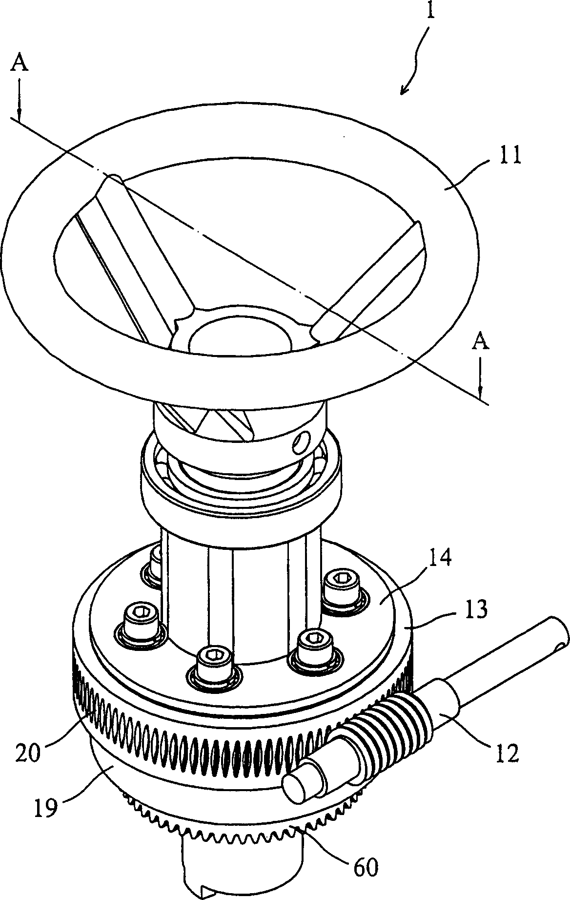
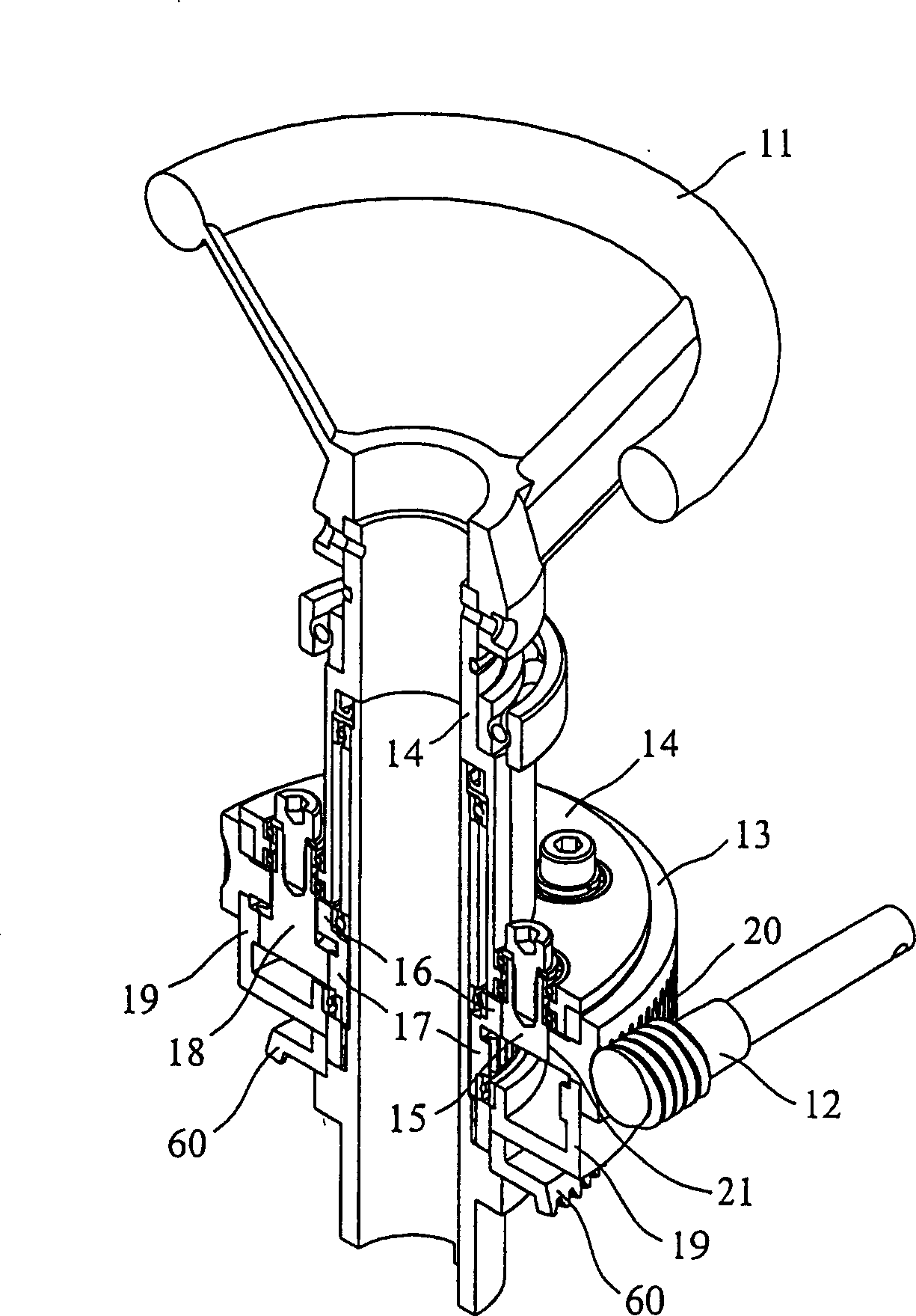
[0053] see figure 1 , showing a perspective view of a two-stage differential planetary gear train driver in Embodiment 1 of the present invention, figure 2 for figure 1 Sectional view of midline A-A. The two-stage differential planetary gear train driver 1 of this embodiment includes: a hand wheel 11, a first stage planetary gear set, a second stage planetary gear set and a worm 12, and the hand wheel 11 is locked and connected to the first stage The swing arm drive element 14 of the planetary gear set, the first stage planetary gear set includes a fixed ring element 13, a swing arm drive element 14, the upper planetary gear set passive element 15 and the upper sun gear passive element 16, the second stage The planetary gear set includes a lower sun gear drive element 17 , a lower planeta...

Embodiment 2

[0056] Embodiment 2: The reduction ratio of the planetary gear set is low to be suitable for multi-rotation valve drivers (in this embodiment, a power is input via a motor)

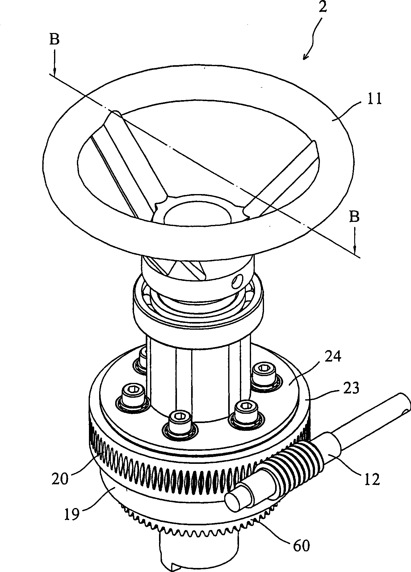
[0057] see image 3 , showing a perspective view of the two-stage differential planetary gear train driver in Embodiment 2 of the present invention, Figure 4 for along image 3 Sectional view of line B-B in. The two-stage differential planetary gear train driver 2 of this embodiment includes: a hand wheel 11, a first stage planetary gear set, a second stage planetary gear set and a worm 12, and the hand wheel 11 is locked and connected to the first stage The swing arm fixed element 24 of the planetary gear set, the first stage of the planetary gear set includes a swing arm fixed element 24, a driving ring element 23, the upper planetary gear set passive element 15 and the upper sun gear passive element 16, the second stage The planetary gear set includes a lower sun gear drive element 17 , a lower pla...

Embodiment 3

[0061] Embodiment 3: The reduction ratio of the planetary gear set is high to be suitable for the 1 / 4 turn type valve driver (in this embodiment, a power is input through the hand wheel)

[0062] see Figure 5 , showing a perspective view of the two-stage differential planetary gear train driver in Embodiment 3 of the present invention, Figure 6 for along Figure 5 The sectional view of the line C-C (omit the spur gear 53, the worm 54 and the hand wheel 55). The two-stage differential planetary gear train driver 3 of this embodiment includes: a spur gear 53, a first stage planetary gear set, a second stage planetary gear set and a hand wheel 55, and the first stage planetary gear set includes a spiral arm Fixed element 34, a driving ring element 33, an upper planetary gear set passive element 35 and an upper sun gear passive element 36, and the second stage planetary gear set includes a lower sun gear driving element 37, a lower planetary gear set driving element 38 and a ...


PUM


Abstract

The invention discloses a two-stage differential planetary gear driver, which comprises the first planetary gear group and the second planetary gear group. Wherein, the first planetary gear group comprises a fixing element, a drive element, the first driven element and the second driven element; the second planetary gear group comprises the first drive element, the second drive element and one driven element, while the first and second driven elements of said first planetary gear group are connected to the first and second drive elements of said second planetary gear group. The invention is a device with high flexible reducing rate without clutch while it can be handful operated and automatically operated synchronously. The output axle of said invention has the retaining function with high reducing transmission efficiency which can apply the 1 / 4 rotational or multi-rotational driver.

Description

technical field [0001] The invention relates to a two-stage differential planetary gear train driver, in particular to a two-stage differential planetary gear train driver with highly elastic reduction ratio and high transmission efficiency. Background technique [0002] When the power of the valve electric drive fails, it needs to rely on manual operation to switch for safety reasons. A clutch method such as US Publication No. 4474078 and No. 4546671 is used to optionally connect manual or motor operation, and Connect and drive the reduction gear for forward and reverse output. Among them, the traditional clutch of the US Patent No. 4474078 is engaged with the handwheel drive mechanism or the motor drive mechanism and is manually switched; the traditional manual electric valve driver of the US Patent No. 4546671 maintains the reliability of long-term use. And the driving gear device can only be transmitted in a low-speed mode with a high reduction ratio because it can resi...

Claims


Application Information

Patent Timeline
IPC IPC(8): F16H3/62
Inventor 林进顺仲之豪周宗易古嘉琳
Owner METAL INDS RES & DEV CENT
Learn More