
Hydraulic flexible method for producing cold-drawn pipe and apparatus

A cold-drawn and flexible technology, applied in wire drawing dies, mandrels, etc., can solve the problems of affecting product accuracy, lack of reliable control, lubricant leakage, etc., to achieve simple and convenient operation, eliminate vibration, and reduce manufacturing costs. Effect

Inactive Publication Date: 2006-07-19
TAIYUAN UNIVERSITY OF SCIENCE AND TECHNOLOGY
View PDF0 Cites 18 Cited by
  • Summary
  • Abstract
  • Description
  • Claims
  • Application Information

AI Technical Summary

Problems solved by technology

The common disadvantage of mechanically driven cold drawing equipment is that vibration will be generated during the drawing process, which cannot ensure that the grains of the workpiece material are formed along the cold drawing direction, especially the chain transmission mechanism, which will produce periodic impact after the chain sprocket wears out , this discontinuity of operation is the fatal factor for the unreliable control of steel pipe quality, which directly affects the accuracy of the product
This kind of facility is prone to problems of lubricant leakage and pressure drop. Therefore, it is difficult to establish a stable lubricating oil film, and it is difficult to design the length of the booster tube. Often, the tube will be pulled out at the beginning of the drawing.
In addition, soap is generally used as a lubricant for forced lubrication of pipes. Although hydrodynamic lubrication can be established, the surface of the pulled out pipe has scratches, the quality is poor, and a coating process is required before drawing; when the pressure increases, the lubricant The viscosity of the metal is reduced, and sometimes the metal bonding phenomenon cannot be avoided, which seriously damages the drawing process and can damage the mold and core.
The above shortcomings limit the application of forced lubrication on cold drawn pipes

Method used


Image

  • Hydraulic flexible method for producing cold-drawn pipe and apparatus
  • Hydraulic flexible method for producing cold-drawn pipe and apparatus
  • Hydraulic flexible method for producing cold-drawn pipe and apparatus

Examples


Embodiment Construction

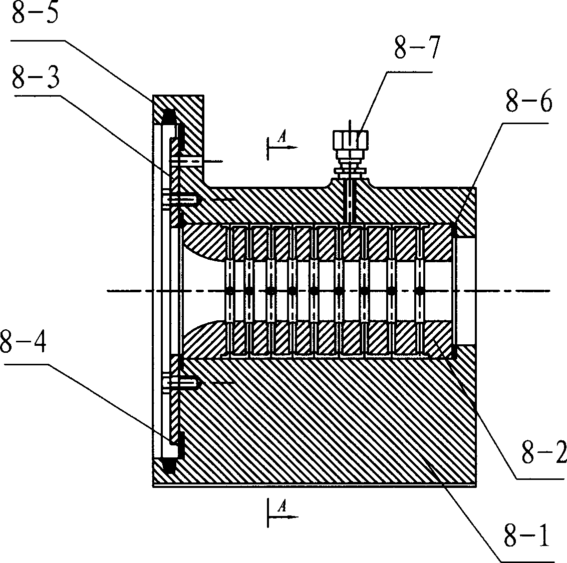
[0055] The specific process steps of a kind of hydraulic flexible cold drawn pipe method are:

[0056] (1) Start to push the assembly oil cylinder 3, and pull the assembly 5 and the mold 8 to separate;

[0057] (2) The feeding frame 7 rises to make the tube blank 12 in place;

[0058] (3) Start the mandrel pushing oil cylinder 2, insert the mandrel 5-5 into the tube blank, push the tube blank into the mold 8, and the loading rack 7 descends;

[0059] (4) Push the combined body oil cylinder 3 to push the combined body 5 to the mold base, and at the same time, the piston 5-3 follows the movement, and the cylinder body 5-1 and the mold base 8-1 port are closed to complete the sealing;

[0060] (5) Start to push the piston oil cylinder 1, and push the piston 5-3 of the assembly 5 to support the tail of the tube blank;

[0061] (6) The clamping mechanism 10 acts to clamp the tube blank 12;

[0062] (7) start drawing oil cylinder 11, start drawing;

[0063] (8) The oil pressure ...


PUM


Abstract

The invention discloses a hydraulic flexible cold-drawing method and equipment in the metallurgical mechanic pipe moulding technique, which comprises the following parts: pushing piston cylinder, pushing core bar cylinder, pushing assembly cylinder, assembly, rail, feeding structure, mould, blanking structure, clamp structure and drawing cylinder. The mould doesn't touch the deformation metal to form the flexible deformation state of mould-hydraulic oil-hollow billet-hydraulic oil-core head, which improves the precision of cold-drawing pipe.

Description

technical field [0001] The invention belongs to the pipe forming technology of metallurgical machinery, and relates to a method and equipment for producing high-precision cold-drawn pipes by adopting hydraulic transmission and flexible forming. It can be used in toner cartridges of photosensitive equipment, shock absorbers of automobiles and motorcycles, bushings of hydraulic cylinders, printing machinery, aviation equipment and other fields. Background technique [0002] In my country, for precision steel pipes such as hydraulic and pneumatic cylinders, the method of hot-rolled seamless pipes by cutting is generally used, while in foreign countries, the technology of cold-drawn pipes without cutting is adopted. Cold drawing machine for plastic deformation of cold working method. The cold drawing machine of prior art is divided into various types such as chain type, rack type, lead screw type, steel rope type, hydraulic type by transmission mode. The common disadvantage of ...

Claims


Application Information

Patent Timeline
IPC IPC(8): B21C1/22B21C1/24B21C3/14B21C3/16B21C1/34
Inventor 双远华胡鸿产
Owner TAIYUAN UNIVERSITY OF SCIENCE AND TECHNOLOGY
Learn More