
Pipe pulse stream generator

A pulse flow generator and generator technology, applied in the direction of fluid flow, mechanical equipment, etc., can solve the problems of high energy consumption and large resistance loss, and achieve the effect of improving thermal efficiency, improving thermal efficiency, and reducing resistance loss

Inactive Publication Date: 2006-07-12
CHONGQING UNIV
View PDF1 Cites 10 Cited by
  • Summary
  • Abstract
  • Description
  • Claims
  • Application Information

AI Technical Summary

Problems solved by technology

[0002] At present, the long-distance transportation of natural gas and oil has the disadvantages of large resistance loss and high energy consumption. Recent studies have shown that the use of pulsed flow can greatly reduce the resistance loss of natural gas transportation.

Method used


Image

  • Pipe pulse stream generator

Examples


Embodiment Construction

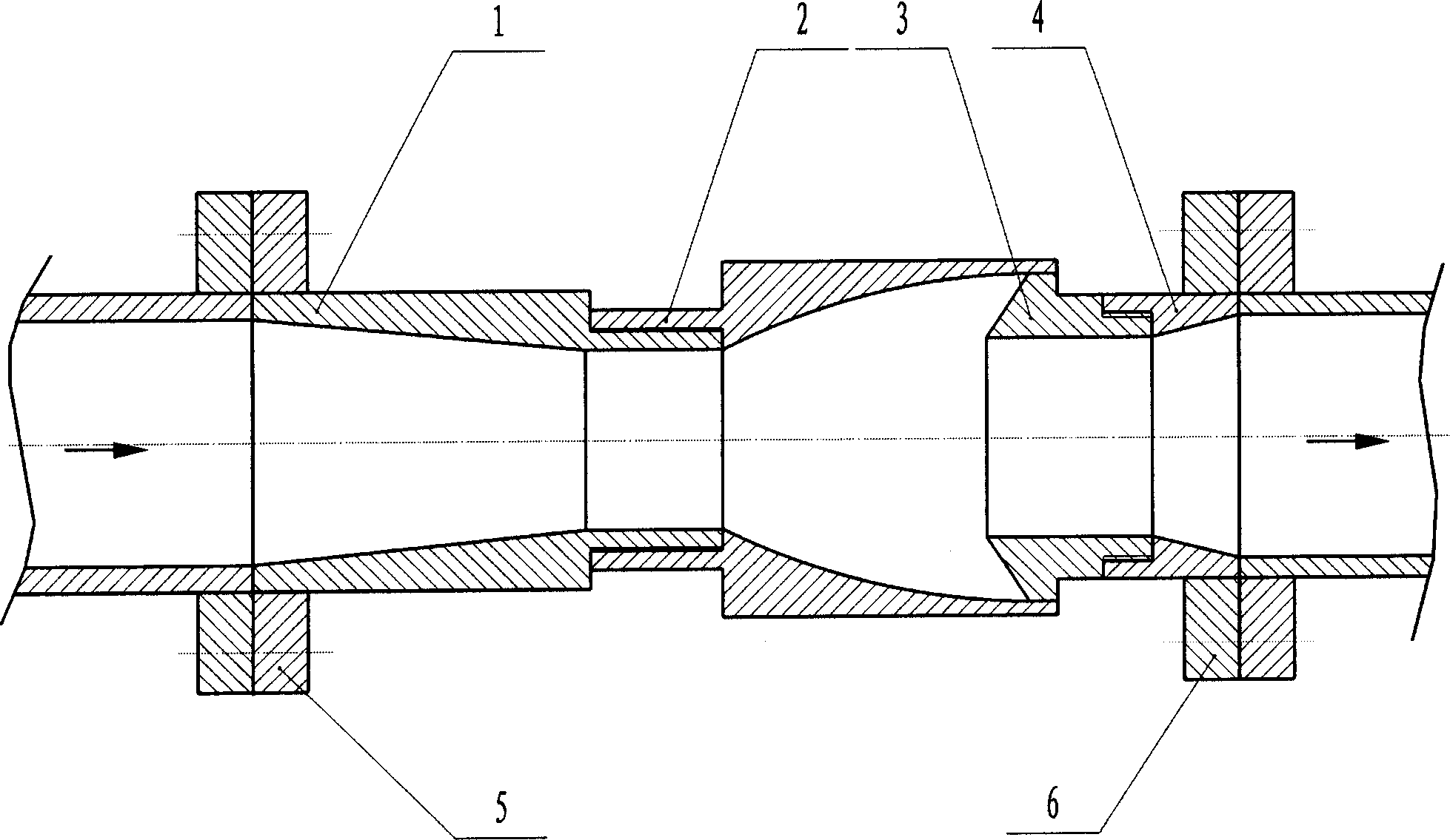
[0016] The upper nozzle body 1, the self-excited oscillation cavity 2, the lower nozzle body 3 and the short pipe 4 are sequentially installed on the same axis. The upper nozzle body 1 has a cone angle of 13°, a conical hole whose length is 7 times the outlet diameter of the upper nozzle body 1, and a through hole whose length is equal to the round hole of the outlet diameter of the upper nozzle body 1. The lower nozzle body 3 The cone angle of the frustum of the front end is 110°, and the outlet hole end of the lower nozzle 3 is equipped with a through-hole pipe 4 with an inner cone angle of 25°.

[0017] The upper nozzle body 1 and the input pipeline are sealed and fixedly connected through the flange plate 5, and the connection mode between the upper nozzle body 1 and the self-excited oscillation cavity 2 is threaded connection or flange plate sealed and fixed connection. The opening end of the self-excited oscillation cavity 2 is fixedly connected with the lower nozzle bod...


PUM


Abstract

The invention relates to a pipe impulse flow generator, belonging to the heat-matter transmission high-efficiency energy-saving device of natural gas and oil. The invention can reduce the resistance of transmitting liquid, save energy, decrease the deposition of olefin, and improve the heat efficiency of transmitting heat and matter. The invention comprises a upper nozzle, a self-excite chamber, a lower nozzle, and a pipe which are sequentially sealed, fixed and connected; the inlet of upper nozzle and the outlet of pipe are individually connected to the inlet and outlet pipe. The invention can use said generator to transform the continuous liquid via the self-excite chamber into impulse liquid without any auxiliary device, and improved amplitude of output pressure as 15-30%, increased impulse frequency from tens to hundreds, to reduce the resistance, save energy consumption and apply variable industries.

Description

Technical field: [0001] The invention relates to a high-efficiency energy-saving device for natural gas, petroleum, heat transfer and mass transfer. The device can be widely used in the long-distance transportation of natural gas and oil to reduce energy consumption, and can also be used to improve the efficiency of heat transfer and mass transfer. Background technique: [0002] At present, there are disadvantages of large resistance loss and high energy consumption in the long-distance transportation of natural gas and oil. Recent studies have shown that the use of pulsed flow can greatly reduce the resistance loss of natural gas transportation. The utility model patent number is 89201391.5, and its invention name is "oscillating pulse jet nozzle for roller cone bit". The nozzle is composed of upper and lower nozzle bodies. , the shape of the upper nozzle body is a stepped cylinder, the flow channel in the nozzle body is composed of two exponential curved surfaces and thre...

Claims


Application Information

Patent Timeline
Patent Type & Authority Applications(China)
IPC IPC(8): F15D1/00
Inventor 廖振方陈德淑康勇烽
Owner CHONGQING UNIV
Learn More