Controlling device of permanent-magnet synchro motor
A permanent magnet synchronous and control device technology, applied in the starting device, single motor speed/torque control, current controller, etc., can solve the problems of insufficient torque, time-consuming, large electric phase angle correction, etc. , to achieve the effect of rapid and smooth start
- Summary
- Abstract
- Description
- Claims
- Application Information
AI Technical Summary
Problems solved by technology
Method used
Image

Examples
Embodiment approach 1
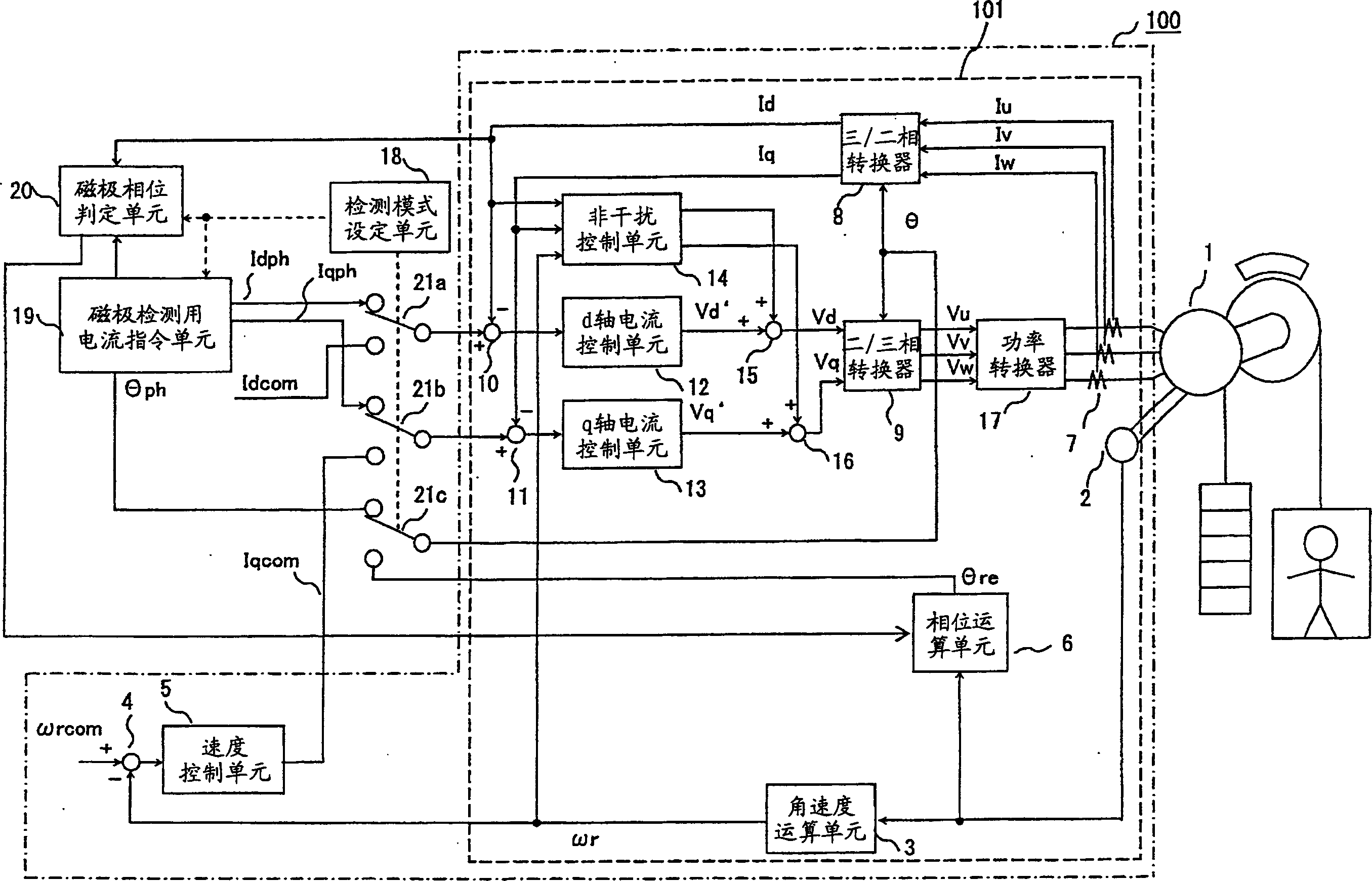
[0024] figure 1 It is a configuration diagram of a control device for a permanent magnet synchronous motor according to Embodiment 1 of the present invention. The control device of this permanent magnet synchronous motor is constituted to include a d-q axis non-interference control system 101 (equivalent to figure 1 The part shown by the dotted line) of the speed control system 100 (equivalent to figure 1 The part shown by the single dot-dash line), and a detection mode setting unit 18, a magnetic pole detection current command unit 19, a magnetic pole phase determination unit 20, and switches 21a to 21c are further added.
[0025] First, the configuration of the speed control system 100 will be described. The d-q axis non-interference control system is conventional, and is used to control the current of the permanent magnet synchronous motor 1, and is a general control method that also includes speed control. The speed control system 100 is composed of a position detector ...
Embodiment approach 2
[0073] In Embodiment 1, the case where the d-axis current command value Idph is increased has been described as a method for easily generating the hunting phenomenon. In Embodiment 2, another method that is likely to cause a hunting phenomenon will be described.
[0074] Such as Figure 4 As shown in the Bode diagram of , the oscillation phenomenon can also be easily generated by delaying the phase in the high-frequency region. Thus, in Figure 5 In the processing of step S512, a delay element (redundant time element) may be inserted into the current control loop instead of increasing the d-axis current command value Idph.
[0075] Figure 7 It is a block diagram showing a d-axis current control system including a delay element 23 and a switch 24 according to Embodiment 2 of the present invention. The delay element 23 outputs the feedback current value Id' having a time delay with respect to the feedback current value Id of the current control system. In addition, the swi...
PUM
 Abstract
Description
Claims
Application Information
 - R&D
- Intellectual Property
- Life Sciences
- Materials
- Tech Scout
- Unparalleled Data Quality
- Higher Quality Content
- 60% Fewer Hallucinations
Browse by: Latest US Patents, China's latest patents, Technical Efficacy Thesaurus, Application Domain, Technology Topic, Popular Technical Reports.
© 2025 PatSnap. All rights reserved.Legal|Privacy policy|Modern Slavery Act Transparency Statement|Sitemap|About US| Contact US: help@patsnap.com