Eureka AIR delivers breakthrough ideas for toughest innovation challenges, trusted by R&D personnel around the world.

Motor control system and rotor position recognition method and device of motor

An identification method and identification device technology, which is applied in the direction of controlling electromechanical transmission devices, control systems, vector control systems, etc., can solve the problems of longer starting time of the motor, affecting the fast and smooth start of the motor, and long time, so as to improve the estimation success rate , The effect of shortening the polarity judgment time

Active Publication Date: 2017-06-06
GUANGDONG WELLING ELECTRIC MACHINE MFG +1
View PDF6 Cites 0 Cited by
  • Summary
  • Abstract
  • Description
  • Claims
  • Application Information

AI Technical Summary

Problems solved by technology

[0003] However, the process of judging the polarity of the motor generally takes a long time, which will cause the starting time of the motor to become longer, which will affect the fast and smooth starting of the motor

Method used


Image

  • Motor control system and rotor position recognition method and device of motor
  • Motor control system and rotor position recognition method and device of motor
  • Motor control system and rotor position recognition method and device of motor

Examples


Embodiment Construction

[0032] Embodiments of the present invention are described in detail below, examples of which are shown in the drawings, wherein the same or similar reference numerals designate the same or similar elements or elements having the same or similar functions throughout. The embodiments described below by referring to the figures are exemplary only for explaining the present invention and should not be construed as limiting the present invention.

[0033] The following disclosure provides many different embodiments or examples for implementing different structures of the present invention. To simplify the disclosure of the present invention, components and arrangements of specific examples are described below. Of course, they are only examples and are not intended to limit the invention. Furthermore, the present invention may repeat reference numerals and / or letters in different instances. This repetition is for the purpose of simplicity and clarity and does not in itself indicat...


PUM


Abstract

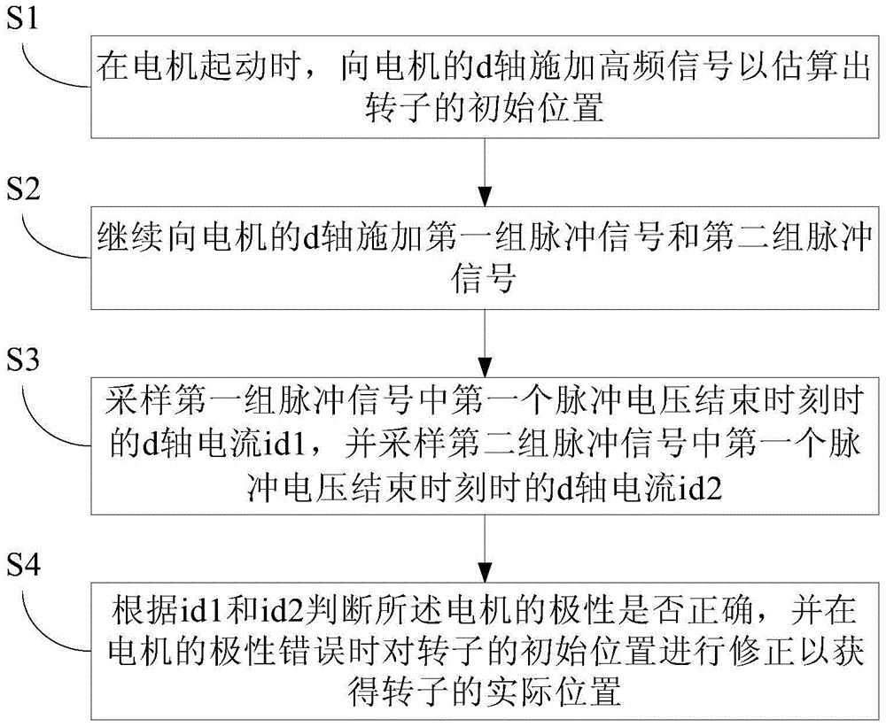
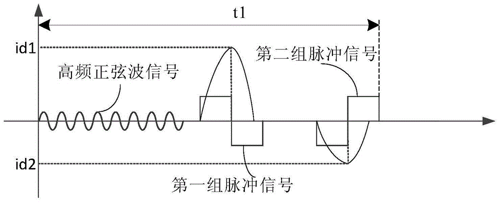
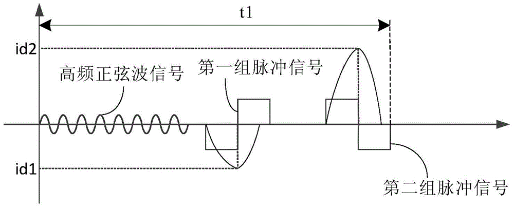
The invention discloses a method for recognizing the position of a rotor of a motor. The method includes the following steps that when the motor is started, a high-frequency signal is applied to a d-axis so as to estimate the initial position of the rotor; a first set of pulse signals and a second set of pulse singles continue to be applied to the d-axis, wherein the first set of pulse signals and the second set of pulse singles respectively comprise two pulse voltages with opposite polarities, and the time sequences of the first set of pulse signals and the second set of pulse singles are opposite; a current id1 of the d-axis is sampled when a first pulse voltage in the first set of pulse signals is finished, and a current id2 of the d-axis is sampled when a first pulse voltage in the second set of pulse signals is finished; whether the polarities of the motor are correct is judged according to the id1 and the id2, and the initial position of the rotor is modified when the polarities are wrong. By means of the method, the initial position of the rotor can be accurately recognized, and quick and smooth start of the motor is guaranteed. The invention further discloses a device for recognizing the position of the rotor of the motor and a motor control system.

Description

technical field [0001] The present invention relates to the technical field of motors, in particular to a method for recognizing the position of a rotor of a motor, a device for recognizing the position of a rotor of a motor, and a motor control system provided with the device for recognizing the position of the rotor. Background technique [0002] In order to ensure the smooth start of the motor, it is necessary to accurately identify the initial position of the rotor of the motor, and in the process of identifying the rotor position, it is necessary to judge the polarity of the motor. [0003] However, the polarity judgment process of the motor generally takes a long time, which will result in a longer starting time of the motor, thereby affecting the fast and smooth starting of the motor. Contents of the invention [0004] The purpose of the present invention is to at least solve the above-mentioned technical drawbacks. [0005] For this reason, the first object of the...

Claims


Application Information

Patent Timeline
Patent Type & Authority Patents(China)
IPC IPC(8): H02P21/18H02P21/34
Inventor 韩建斌
Owner GUANGDONG WELLING ELECTRIC MACHINE MFG
Why Eureka
Eureka Blog
Learn More