
Noise reducing device used for backlight module

A backlight module and noise technology, applied in optics, nonlinear optics, instruments, etc., can solve problems such as increasing complexity and manufacturing cost, increasing dust leakage, and popping noise.

Inactive Publication Date: 2006-06-28
AU OPTRONICS CORP
View PDF0 Cites 0 Cited by
  • Summary
  • Abstract
  • Description
  • Claims
  • Application Information

AI Technical Summary

Problems solved by technology

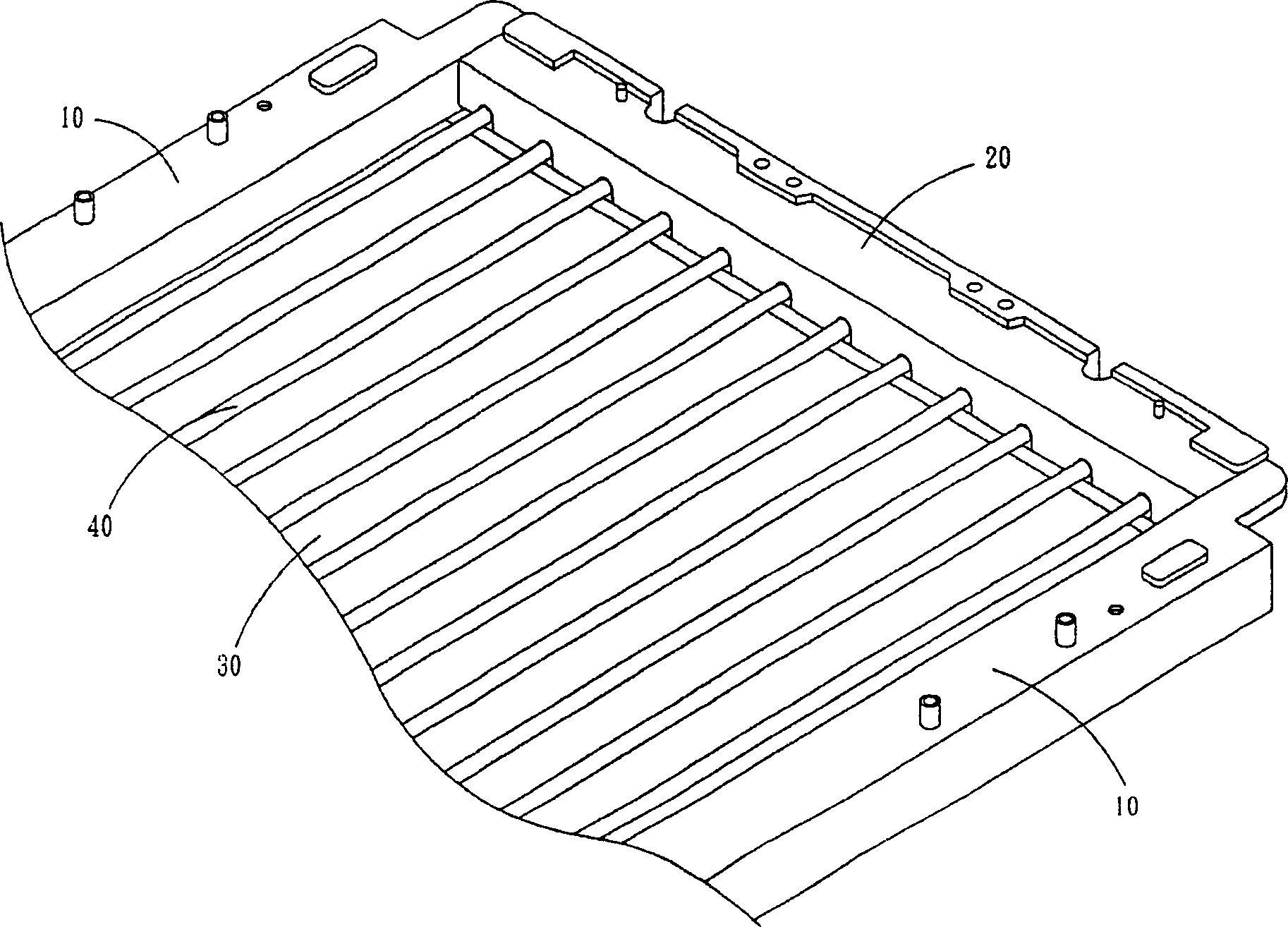
But this method still has disadvantages, because the increase of the gap distance will aggravate the dust leakage problem of the backlight module that needs to be overcome.
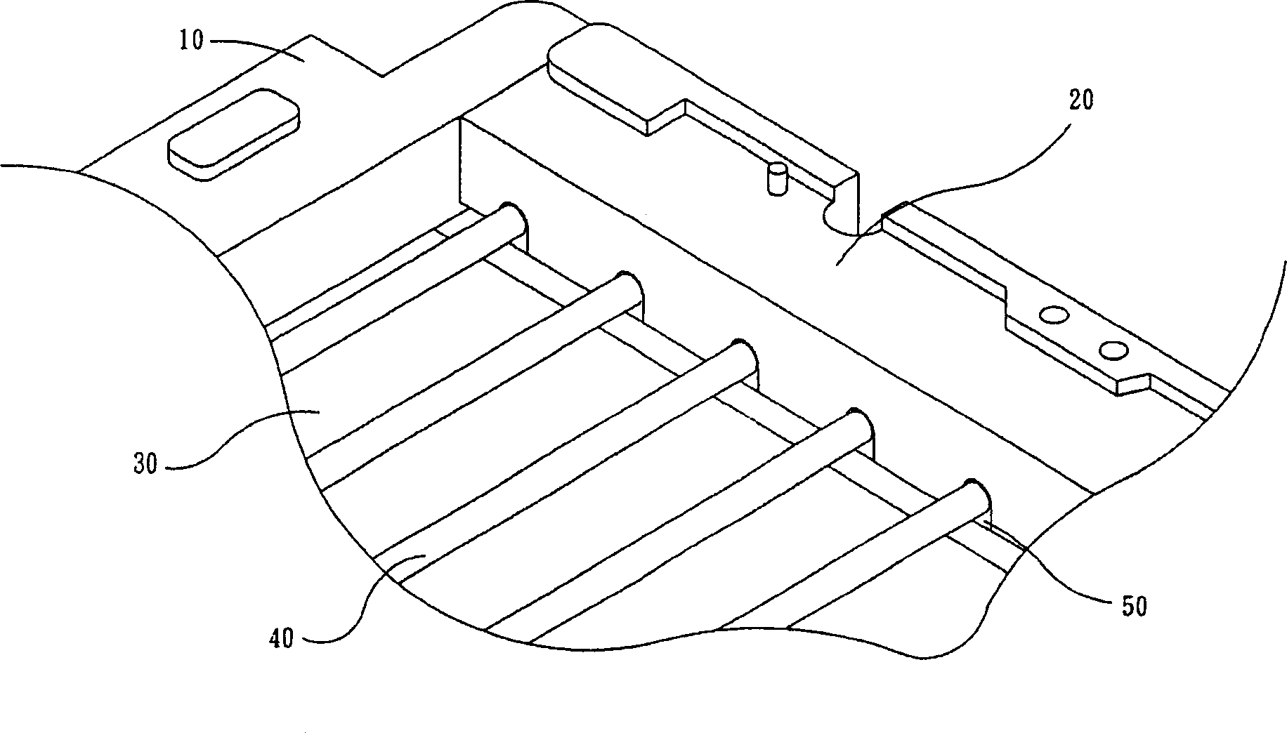
In other words, increasing the gap distance between the back frame 10 and the lamp tube fixing frame 20 can certainly solve the problem of popping noise caused by thermal expansion and contraction, but on the other hand, it will also increase the amount of dust leakage, so this is not a perfect solution. the solution
In addition, another solution of the known technology is to attach a strip of double-sided adhesive tape between the back frame 10 and the lamp tube fixing frame 20 to solve the above-mentioned burst noise problem. Although this method reduces dust leakage, it increases the Manufacturing process complexity and manufacturing cost

Method used


Image

  • Noise reducing device used for backlight module
  • Noise reducing device used for backlight module
  • Noise reducing device used for backlight module

Examples


Embodiment Construction

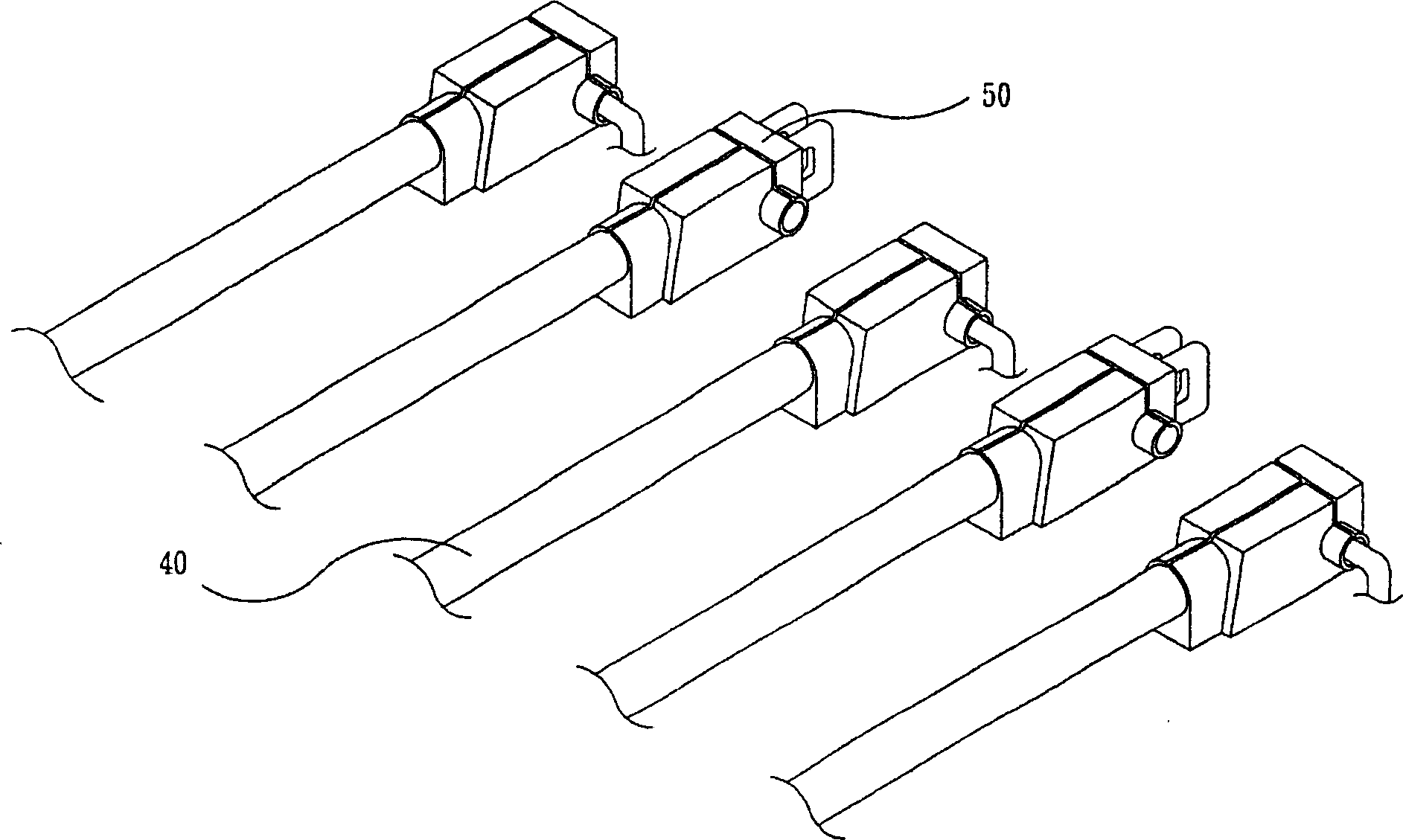
[0017] refer to Figure 4 , which shows an embodiment of applying the present invention in a backlight module. For the sake of illustration, Figure 4 The illustrated embodiment is relative to the image 3 It is drawn with the known technology shown in order to clearly illustrate the technical features of the present invention. Figure 4 It shows a noise reduction device 500 used in the backlight module and a lamp tube group for providing the light source required by the backlight module. The lamp tube group preferably includes a plurality of parallel arranged lamp tubes 400, wherein the noise reduction device 500 The main components include a plurality of bodies 510 and extensions 520 . And each body 510 includes a groove, in order to provide the embedding space (not shown in the figure) of each lamp tube 400 end, and fix these lamp tubes 400, dispose in the structure of the body 510 the circuit that conducts with the backlight module ( not shown in detail), and further f...


PUM


Abstract

A noise-eliminating device used on back light module consists of multiple noises eliminating components as each component being set with body and extended portion. It features that cracking noise caused by heat expansion and cold shrinkage between lamp fixture unit and back plate frame of back light module can be reduced by damping action of extended portion when back light module is switched on.

Description

technical field [0001] The invention relates to a noise reduction device, in particular to a noise reduction device applied to a liquid crystal display backlight module. Background technique [0002] Due to the advantages of thinness, lightness, power saving and low radiation of liquid crystal displays, liquid crystal displays are widely used in various electronic and consumer products, and direct-lit backlight modules are one of the light-emitting technologies frequently used in liquid crystal displays. The main structure of the liquid crystal display can be roughly divided into two parts: the panel module and the backlight module. The panel module mainly includes an ITO (indium tin oxide referred to as ITO) conductive glass substrate, a liquid crystal layer, an alignment film, a color filter, a polarizer, and a driver IC. and other components. Secondly, the direct type backlight module mainly includes a light source, a light guide plate, a prism sheet, a diffuser plate, a...

Claims


Application Information

Patent Timeline
IPC IPC(8): G02F1/1335G02F1/1333
Inventor 陈信利周斐玲
Owner AU OPTRONICS CORP
Learn More