
Semiconductor chip mounting body and manufacturing method thereof

A chip mounting and manufacturing method technology, applied in semiconductor/solid-state device manufacturing, semiconductor devices, electric solid-state devices, etc., can solve problems such as low bonding strength, reduced electrical characteristics, poor conductivity of conductive adhesives, etc., to achieve improved Effects of productivity and small reliability

Inactive Publication Date: 2006-06-21
KUMAMOTO TECH & IND FOUND
View PDF5 Cites 2 Cited by
  • Summary
  • Abstract
  • Description
  • Claims
  • Application Information

AI Technical Summary

Problems solved by technology

However, conductive adhesives are poor in conductivity, and because of low adhesive strength, there is a disadvantage in that the electrical characteristics of semiconductors that change frequently are degraded with the increase in the age of use.

Method used


Image

  • Semiconductor chip mounting body and manufacturing method thereof
  • Semiconductor chip mounting body and manufacturing method thereof

Examples


Embodiment Construction

[0021] Hereinafter, embodiments of the present invention will be described in detail with reference to the drawings.

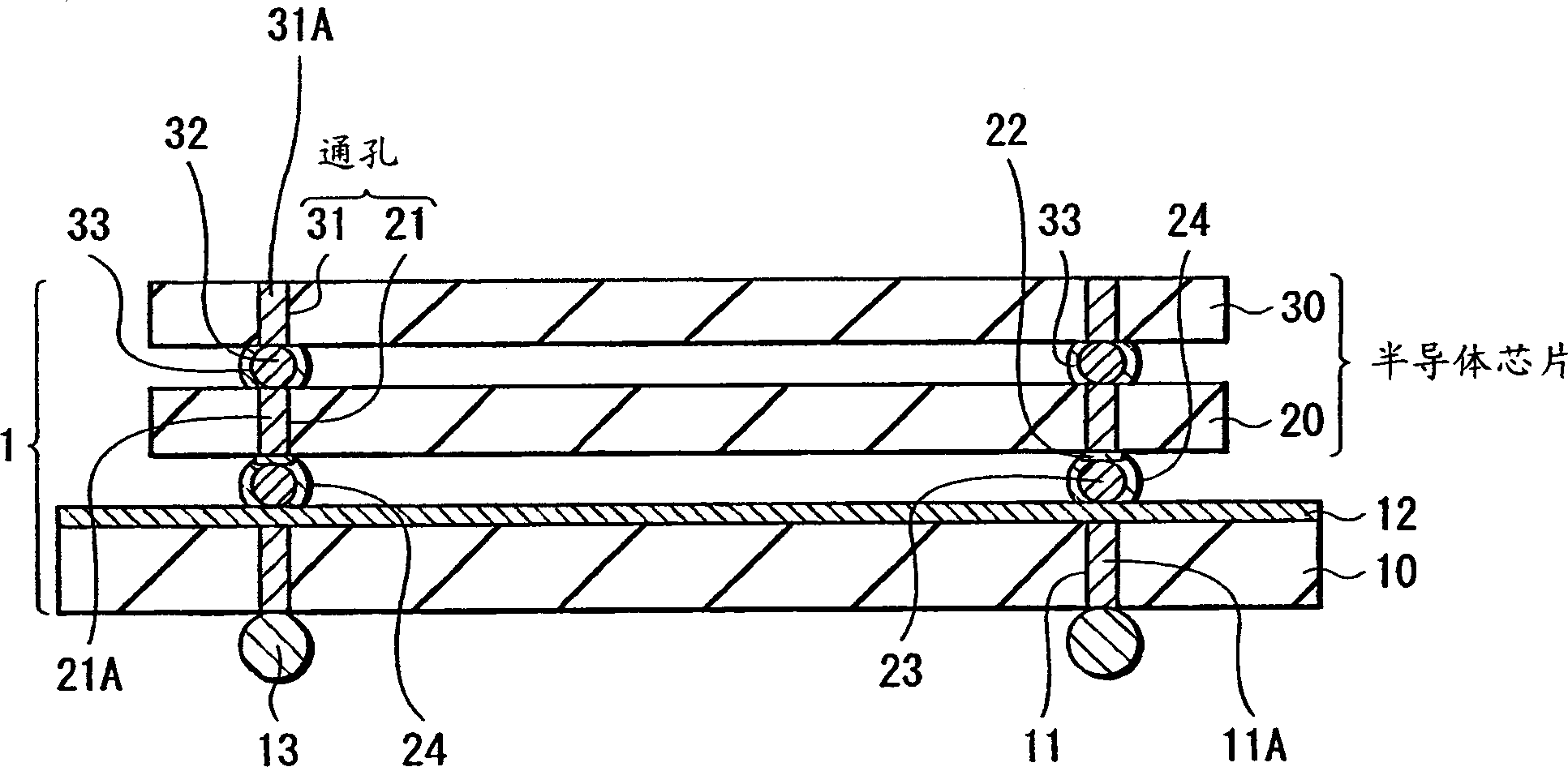
[0022] figure 1 It is a figure which shows the cross-sectional structure of the semiconductor chip package 1 which concerns on one Embodiment of this invention. This semiconductor chip package 1 is a package in which semiconductor chips 20 and 30 having a multilayer structure (here, two layers) are stacked and mounted on a wiring board 10 made of, for example, polyimide resin.

[0023] A through hole (electrode formation hole) 11 is provided in the wiring substrate 10, and an electronic circuit composed of a wiring layer 12 is formed on the surface. Penetrating electrodes 11A are formed on the electrode forming holes 11 . 11 A of external electrodes can be formed by electroplating nickel (Ni) of about 1-150 micrometers, for example. As another method, electrodes may be produced by remelting solder after electroplating.

[0024] Ball electrodes 13 made of,...


PUM


Abstract

A semiconductor chip (20) having protruding electrodes (bumps) (23) on external lead-out electrodes is mounted on a wiring board (10), and a semiconductor chip (30) is mounted on the semiconductor chip (20). Between the wiring layer (12) of the wiring substrate (10) and the protruding electrodes (23) of the semiconductor chip (20), and between the protruding electrodes of the semiconductor chips (20), (30) are electrically connected by electrolytic plating. Between the wiring layer (12) and the protruding electrodes (23) and between the protruding electrodes of the semiconductor chip (20) (30) are stably connected through the plating films (24), (33).

Description

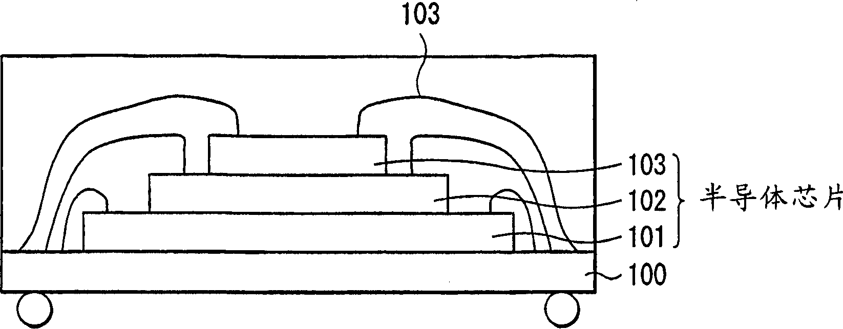
technical field [0001] The present invention relates to a semiconductor chip package in which a plurality of semiconductor chips are flip-chip connected and a method for manufacturing the same. Background technique [0002] In response to social demands for miniaturization and weight reduction of electronic equipment, semiconductor devices such as LSI (Large Scale Integrated circuit) are being further miniaturized and densified. As one of the methods for such miniaturization and high density, stacking of semiconductor chips is being promoted. [0003] Before, such as figure 2 As shown, a small-sized semiconductor chip 102 is mounted on a large-sized semiconductor chip 101 mounted on a wiring substrate 100 through an adhesive or the like. Resin sealing performs lamination of such semiconductor chips. In order to achieve further miniaturization and higher density, it is necessary to make each chip thinner while reducing the size of the semiconductor chip. [0004] However,...

Claims


Application Information

Patent Timeline
Patent Type & Authority Applications(China)
IPC IPC(8): H01L25/065H01L21/60
CPCH01L2224/48227H01L2924/01078H01L2924/10253H01L2924/30107
Inventor 大野恭秀
Owner KUMAMOTO TECH & IND FOUND
Learn More