
Electronic equipment temperature control system and method

A technology of a temperature control system and a temperature control method, applied in the direction of temperature control, control/regulation system, non-electric variable control, etc., can solve the problems of poor air-cooling heat dissipation effect, many fan failures, and unsealed radiation of the chassis. The temperature can be controlled in a large range, the electromagnetic radiation is reduced, and the heat dissipation performance is superior.

Inactive Publication Date: 2006-06-21
LENOVO (BEIJING) LTD
View PDF6 Cites 5 Cited by
  • Summary
  • Abstract
  • Description
  • Claims
  • Application Information

AI Technical Summary

Problems solved by technology

The disadvantage of this heat dissipation method is: it is necessary to install an air conditioner to reduce the temperature of the computer room, so that both the fan and the air conditioner will generate a lot of noise; in addition, the cooling fan is prone to failure; The body is healthy; and the CPU operating temperature and the temperature inside the chassis are higher than room temperature
The disadvantage of this heat dissipation method is that it cannot be adaptively adjusted, and the operating frequency of the entire refrigeration system cannot be dynamically adjusted according to the temperature of the components to achieve energy-saving and quiet effects; Differences (for example, the temperature of the CPU is generally higher than the temperature of the hard disk), different control strategies are adopted
[0008] In order to solve the defects of poor heat dissipation effect of air-cooled heat dissipation, high noise, frequent fan failures and radiation leakage, as well as the shortcomings of the existing vapor compression refrigeration that cannot be adaptively adjusted and cannot be distributed, it is necessary to Provide a new system and method for temperature control of electronic equipment

Method used


Image

  • Electronic equipment temperature control system and method
  • Electronic equipment temperature control system and method
  • Electronic equipment temperature control system and method

Examples


Embodiment Construction

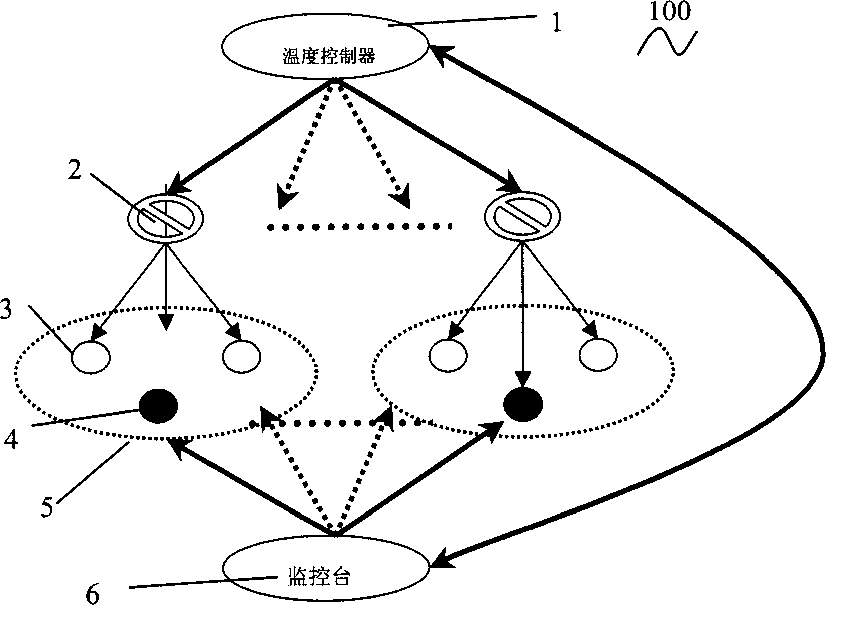
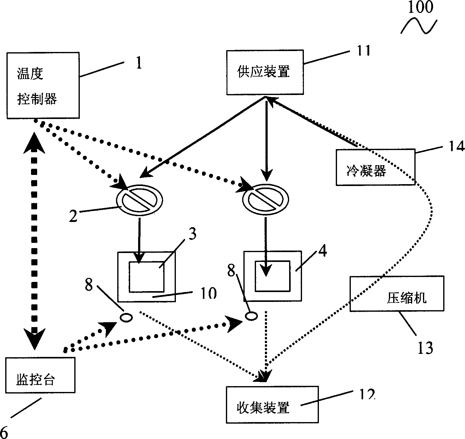
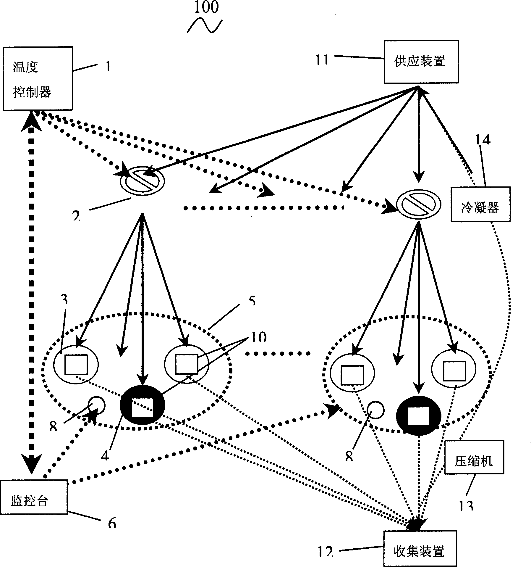
[0031] Such as figure 1 As shown, the electronic device temperature control system 100 of the present invention includes a temperature controller 1, an expansion valve 2, an evaporator (not shown) arranged on the heat-generating components 3, 4, monitoring the temperature of the components 3, 4 and communicating with the temperature controller 1 Monitoring stations 6 that communicate with each other. To illustrate the principle more clearly, take an expansion valve controller in which the temperature controller controls the temperature by controlling the expansion valve as an example.

[0032] The components 3, 4 are refrigerated by a vapor compression refrigeration method, and are divided into different element groups 5 according to their normal operating temperature ranges. For example, there are two computers, in which the components that need heat dissipation and temperature control include CPU A, CPU B, chip A, chip B, hard disk A, and hard disk B. The normal temperature...


PUM


Abstract

The invention discloses a temperature control system for an electronic element, which comprises: an evaporator, an expansion valve to transmit liquid refrigerant for said evaporator, a temperature controller, and a console to monitor the temperature of heat part. This invention can achieve silencing effect easily in room; can be used on computer to make cabinet much thin for a little space as well as sealing to reduce electromagnetic radiation on maximum limit. This invention also provides an adaptive and distributed temperature control method.

Description

technical field [0001] The invention relates to an electronic equipment temperature control system and method, in particular to an adaptive and distributed electronic equipment temperature control system and method. Background technique [0002] Currently known main heat dissipation methods include air cooling, semiconductor refrigeration, vapor compression refrigeration, heat pipe technology, and liquid cooling. Among them, air cooling is the mainstream in the current market. The above-mentioned various heat dissipation methods all have some factors that affect the speed of heat dissipation, and these factors have become relatively difficult shortcomings in the above-mentioned several heat dissipation methods. [0003] First of all, the biggest advantage of air-cooled heat dissipation is low cost, but because the fan is placed perpendicular to the motherboard, the size of the fan is limited by the thickness of the fuselage, so the heat dissipation efficiency is also limite...

Claims


Application Information

Patent Timeline
Patent Type & Authority Applications(China)
IPC IPC(8): H05K7/20F25B1/00G05D23/00
Inventor 柯海滨何士贵董静静
Owner LENOVO (BEIJING) LTD
Learn More