
Method for manufacturing transparent anode and electrode lead wire of organic luminescent display unit

A light-emitting display device and electrode extraction technology, applied in the direction of electroluminescent light source, light source, electric light source, etc., can solve the problems of reducing device yield, affecting device luminous brightness, and luminous efficiency. Possibility of impurity contamination, effect of improving performance and life

Inactive Publication Date: 2006-06-21
INESA ELECTRON
View PDF0 Cites 6 Cited by
  • Summary
  • Abstract
  • Description
  • Claims
  • Application Information

AI Technical Summary

Problems solved by technology

Organic substances and other impurities remaining on the surface of ITO will cause short circuit and open circuit of cathode and anode in organic electroluminescent display devices, forming broken lines and cross lines on the display screen, and alignment errors will also cause cross lines, which will affect the device The luminous brightness, luminous efficiency, device life and other properties reduce the yield of devices

Method used


Image

  • Method for manufacturing transparent anode and electrode lead wire of organic luminescent display unit
  • Method for manufacturing transparent anode and electrode lead wire of organic luminescent display unit
  • Method for manufacturing transparent anode and electrode lead wire of organic luminescent display unit

Examples


Embodiment Construction

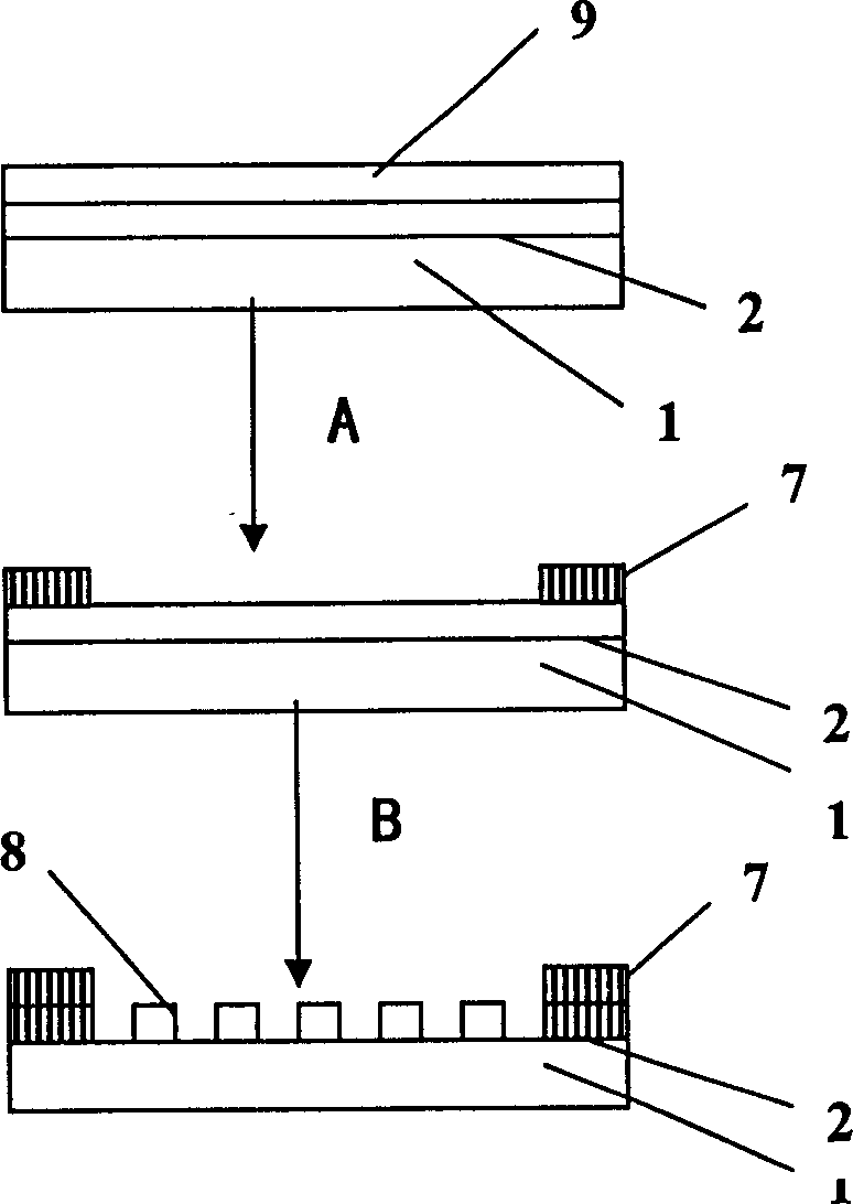
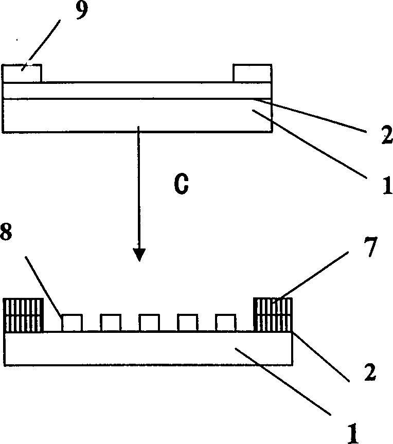
[0019] see figure 2 As shown, in the embodiment of the present invention, the steps of the manufacturing method of the transparent anode and the electrode lead wire of the organic light emitting display device are as follows:

[0020] Make a mask: Make a mask for metal sputtering according to the design plan;

[0021] Sputtering metal layer 9: use the mask plate to directly sputter the metal layer 9 of the required electrode lead-out line part on the glass substrate 1 of the ITO transparent conductive film 2 according to the technical indicators such as thickness and material; the electrode lead-out line is generally Use metals with excellent electrical conductivity, such as chromium, etc. This metal has strong adhesion to the ITO glass substrate, high firmness, and strong wear resistance. In addition, it can have high resolution. In addition, chromium has very good resistance to organic solvents; when it is necessary to form pixels The exposed areas of the lines must not h...


PUM


Abstract

The invention discloses a manufacture method for transparent anode and electrode lead-out wire for organic luminous display unit, which comprises: preparing mask plate; sputtering directly need metal layer of lead-out wire with the mask plate on glass substrate with ITO transparent conductive film; spin coating positive photoresist film; exposing; developing, baking; etching Cr and ITO transparent conductive film; and releasing film. This invention just needs development and releasing-film process for one time, cuts time, and improves yield.

Description

technical field [0001] The invention relates to the technical field of electronic display devices, in particular to the manufacture of substrates of organic electroluminescence display devices. Background technique [0002] The current organic electroluminescent devices are generally composed of upper and lower electrodes and an organic material film with semiconductor properties sandwiched between them. The organic layer film can be prepared by thermal evaporation, spin coating or other film-forming methods. The anode is transparent and conductive indium tin oxide ITO. When a forward DC voltage is applied across the device, it emits light through the injection and recombination of electron and hole carriers. The organic electroluminescence display device is a flat matrix device, and the anode and cathode isolation columns need to be patterned and engraved on a substrate with a certain size and shape. In addition if figure 1 As shown, in order to better increase the conne...

Claims


Application Information

Patent Timeline
Patent Type & Authority Applications(China)
IPC IPC(8): H05B33/10H05B33/26
Inventor 吴玉琦徐进
Owner INESA ELECTRON
Learn More