
Organic sulfur compound containing water discharge apparatus

A treatment device and compound technology, applied in biological water/sewage treatment, water treatment parameter control, sustainable biological treatment, etc., can solve problems such as low decomposition speed, organic matter decomposition, poor decomposition speed, DMS treatment outflow, etc., to achieve Effect of reducing TOC and preventing short flow

Inactive Publication Date: 2006-06-21
KURITA WATER INDUSTRIES LTD
View PDF0 Cites 0 Cited by
  • Summary
  • Abstract
  • Description
  • Claims
  • Application Information

AI Technical Summary

Problems solved by technology

[0005] Like general activated sludge treatment equipment, if all the organic matter is decomposed by a single aeration tank, there is a danger that some of the organic matter will flow out in an insufficiently decomposed state due to the poor decomposition property and decomposition speed of the organic matter.
In particular, when DMSO is decomposed, it is expected that the decomposition speed from DMS to MM will be lower than the decomposition speed from DMSO to DMS, and the DMS will flow out without sufficient treatment.

Method used


Image

  • Organic sulfur compound containing water discharge apparatus
  • Organic sulfur compound containing water discharge apparatus
  • Organic sulfur compound containing water discharge apparatus

Examples


Embodiment 1

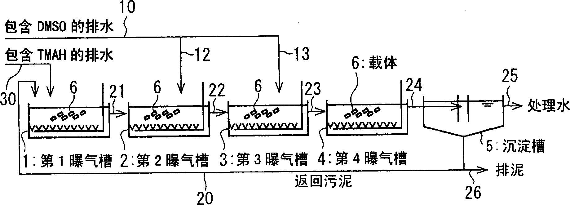
[0084] exist figure 1 In the shown device, untreated water is injected into each aeration tank of the first to fourth aeration tanks 1 to 4 at a flow rate of 15 L / h each time to treat it. In addition, nitrogen and phosphorus were added to untreated water, and water was passed so that BOD:BOD:N:P=100:5:1 (weight ratio) was assumed to be 3 times TOC.

[0085] The water quality of the obtained treated water and the DMS concentration in the exhaust gas of each aeration tank were investigated, and the results are listed in Table 1.

Embodiment 2

[0087] use figure 2 In the shown device, untreated water is injected into the first to third aeration tanks 1 to 3 at a flow rate of 20 L / h each time, and it is treated in the same manner as in Example 1 except that, The water quality of the obtained treated water and the DMS concentration in the exhaust gas of each aeration tank are listed in Table 1.

Embodiment 3

[0089] picture image 3 As shown, in each of the aeration tanks 1 to 4, the apparent capacity is used to add a square sponge with a side length of 3mm according to 30% of the tank capacity, and each time the untreated Water is injected into the second to third aeration tanks 2 and 3, respectively, and the following water quality containing TMAH is supplied to the first aeration tank. In the untreated water, three times the TOC is assumed as BOD, Add phosphorus in the ratio of BOD: P=100: 1 (weight ratio), in addition, according to the mode identical with embodiment 1, it is processed, the water quality of the treated water that has obtained and each aeration tank exhaust DMS concentrations are listed in Table 1.

[0090] (Drainage including TMAH)

[0091] Soluble TOC: 32.8mg / L

[0092] TMAH: 53.8mg / L

[0093] Nitrogen by Keidel method: 12.3mg / L


PUM

PropertyMeasurementUnit
solubility (mass)aaaaaaaaaa

Abstract

By installing two or more aerobic biological reaction tanks in series, whenever the wastewater containing organic sulfur compounds is treated, the odor generated can be reduced with simple equipment, and stable treatment can be performed to obtain good results. Treated water of high quality. More than two aerobic biological reaction tanks (1-4) are connected in series, and the wastewater containing organic sulfur compounds is respectively injected into more than two aeration tanks (1-4). Since the BOD load of each reaction tank injected is reduced by separately injecting wastewater containing organic sulfur compounds, even if the oxygen requirement of each reaction tank is reduced, it can still be performed without using a special aeration device. Prevents situations where you are easily exposed to hypoxia. Thereby, the odor by generation|occurrence|production of DMS and MM in reducing atmosphere by oxygen deficiency is reduced.

Description

technical field [0001] The present invention relates to a device for biologically treating wastewater of organic sulfur compounds containing DMSO (dimethyl sulfoxide), sulfonic acids, etc. A treatment device for treating waste water containing organic sulfur compounds to obtain good water quality. Background technique [0002] In recent years, DMSO has been widely used in semiconductor manufacturing processes and liquid crystal panel manufacturing processes. For example, in the liquid crystal panel manufacturing field, a cleaning agent obtained by adding DMSO to diethylene glycol monobutyl ether, 2-aminoethanol, 2,2-aminoethyl aminoethanol, etc. is used. Therefore, the treatment method of these waste water containing DMSO becomes important. [0003] Since DMSO is biodegradable, it is economical to perform biological treatment. However, if biological treatment is performed on wastewater containing DMSO, there is a problem of generating odor from the aeration tank and the tr...

Claims


Application Information

Patent Timeline
Patent Type & Authority Applications(China)
IPC IPC(8): C02F3/02
CPCY02W10/10C02F3/121C02F2101/101C02F2209/06C02F2209/22C02F2303/02
Inventor 田中伦明川胜孝博
Owner KURITA WATER INDUSTRIES LTD
Learn More