
Speed controller of synchronous motor

A control device and pulse width control technology, applied in the direction of motor generator control, AC motor control, single motor speed/torque control, etc., can solve the problem of difficult to reproduce current, difficult to achieve high-speed and high-performance Harmonic increase and other issues

Inactive Publication Date: 2006-06-07
HITACHI JOHNSON CONTROLS AIR CONDITIONING INC
View PDF3 Cites 6 Cited by
  • Summary
  • Abstract
  • Description
  • Claims
  • Application Information

AI Technical Summary

Problems solved by technology

That is, in the current reproduction method, since the motor current is reproduced based on the DC current of the inverter and the gate pulse signal of the inverter, when the command voltage is low and the pulse width of the gate pulse is extremely short at the time of starting, etc., It is difficult to capture the current component of the motor
In particular, when the speed of the motor is increased, the higher the average switching frequency (carrier frequency) of the inverter is set, the shorter the pulse width of the gate pulse is, and the more difficult it is to reproduce the current
As a countermeasure against this, the carrier frequency of the inverter is reduced only when the motor is started. Causes of Harsh Electromagnetic Noise
[0011] In this way, when the "magnetic pole position sensorless control method" and the "current reproduction method" are combined, when the motor is rotated at a high speed, for example, at a frequency of 400 Hz or more, the calculation cycle must be accelerated according to the carrier frequency. There is a limitation in the gate pulse width, so it is difficult to speed up the operation cycle alone
Therefore, it is difficult to realize a high-speed and high-performance synchronous motor control device without both the magnetic pole position sensor and the current sensing device.

Method used


Image

  • Speed controller of synchronous motor
  • Speed controller of synchronous motor
  • Speed controller of synchronous motor

Examples


Embodiment Construction

[0062] Hereinafter, an embodiment of the present invention will be described with reference to the drawings.

[0063] Embodiment 1

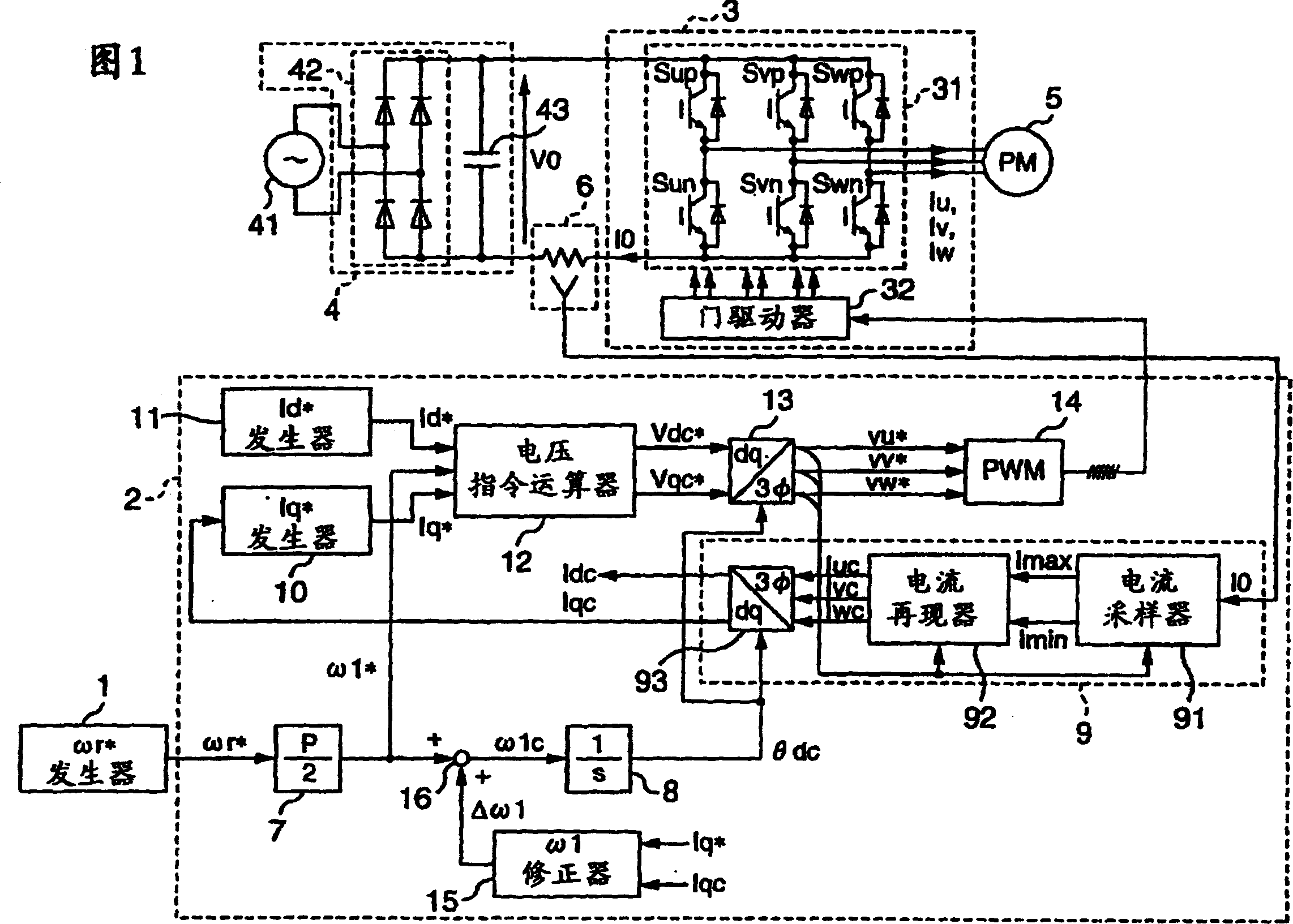
[0064] Fig. 1 is a block diagram showing a system configuration of Embodiment 1 of a speed control device for a synchronous motor according to the present invention. In Fig. 1, the speed control device of the synchronous motor is constituted as having a generator for providing the rotational speed command ωr to the synchronous motor 5 * The revolution command ωr * The number of revolutions instruction generator 1 of computing; The AC applied voltage of synchronous motor 5 is calculated, according to this calculation result, generates the pulse width modulation signal (PWM signal) as pulse width control signal, is applied to the controller 2 on the inverter 3; Inverter 3 driven by this PWM signal; DC power supply 4 to supply power to inverter 3; current detector (inverter current The detector) 6 is connected to the AC output side of the inverte...


PUM


Abstract

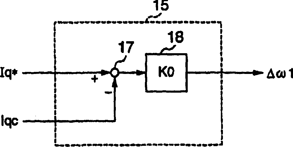
The invention provides a speed control device of a synchronous motor. Obtain the electrical angular frequency instruction ω1* from the rotation instruction ωr*, obtain the correction amount Δω1 from the difference between Iq* and Iqc, add ω1* and Δω1 to obtain ω1c, use the integrator (8) to integrate ω1c to obtain the AC phase θdc, The current 10 detected by the current detector (6) is sampled with the current sampler (91), and the alternating current is reproduced with the current reproducer (32). Current carries out coordinate transformation, asks Iqc, asks Iq* from Iqc with Iq* generator (10), according to Id*, Iq*, ω*, asks applied voltage instruction Vdc*, Vqc* with voltage command arithmetic unit (12), Use the dq inverse converter (13) to find the three-phase AC voltage command vu*~vw* from these applied voltages, generate a PWM signal with the PWM generator (14) according to the three-phase AC voltage command, and control the inverter according to the PWM signal ( 3).

Description

[0001] This application is a divisional application of the application dated July 3, 2003, the application number is 03146514.5, and the invention name is a speed control device for a synchronous motor. technical field [0002] The present invention relates to a speed control device for a synchronous motor, in particular to a speed control device for a synchronous motor suitable for controlling the speed of the synchronous motor without using a magnetic pole position sensor for detecting the magnetic pole position of the synchronous motor and a current sensor for detecting the current of the synchronous motor . Background technique [0003] As a control method for controlling the speed of a synchronous motor composed of a magnet motor, various methods have been proposed, such as a method not using a magnetic pole position sensor, a method not using a current sensor, and the like. [0004] In the conventional control method, the control method that does not use the magnetic p...

Claims


Application Information

Patent Timeline
Patent Type & Authority Applications(China)
IPC IPC(8): H02P27/04H02P6/06H02P6/08H02P6/18H02P6/182H02P21/00H02P21/13H02P21/14H02P21/18H02P21/24H02P23/14H02P27/06H02P27/08
CPCF25B49/025H02P27/08H02P21/22
Inventor 岩路善尚遠藤常博川端幸雄坂本潔高倉雄八
Owner HITACHI JOHNSON CONTROLS AIR CONDITIONING INC
Learn More