
Rotary scanning passive microwave imaging primary and secondary satellite system

A passive microwave and rotary scanning technology, which is applied in the radio wave measurement system, radio wave reflection/re-radiation, utilization of re-radiation, etc., can solve the problems of increasing system engineering development cost, difficulty, limitation, and reduction of antenna weight and volume. Achieve the effect of simple sub-star attitude stabilization control, simplify system complexity, and improve spatial resolution

Inactive Publication Date: 2006-06-07
NAT SPACE SCI CENT CAS
View PDF0 Cites 13 Cited by
  • Summary
  • Abstract
  • Description
  • Claims
  • Application Information

AI Technical Summary

Problems solved by technology

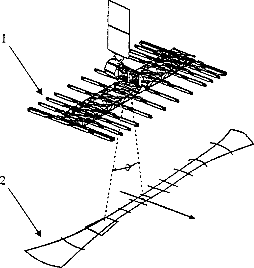
[0012] For the one-dimensional spaceborne system, its disadvantages are: since the real aperture of the waveguide slot antenna is still needed to obtain the spatial resolution in the along-track direction, the further reduction of the weight and volume of the antenna is limited; moreover, when the receiving unit When the one-dimensional linear distribution, it can be proved that the same baseline combination will inevitably appear when the number of units is greater than 4
This is especially prominent in two-dimensional systems. Taking MIRAS as an example, the entire system includes 69 receivers and a digital correlator array with up to 5,000 units. This will undoubtedly increase the cost and difficulty of system engineering development and affect the system work. The stability and system calibration bring great challenges

Method used


Image

  • Rotary scanning passive microwave imaging primary and secondary satellite system
  • Rotary scanning passive microwave imaging primary and secondary satellite system
  • Rotary scanning passive microwave imaging primary and secondary satellite system

Examples


Embodiment 1

[0044] This embodiment takes an interplanetary CME (CME: Coronal Mass Ejection, coronal mass ejection) passive microwave imaging satellite-mother-satellite system as an example. Utilize this embodiment, from the condescending remote sensing observation of the coronal mass ejection event plasma cloud (its plasma density can reach 80 per cubic centimeter near the earth's orbit) sent by the sun from the high-inclination solar polar orbit orbit (apogee 0.5-1.5AU), The speed can reach 1000KM / S), and it is imaged and monitored. Special attention should be paid to the CME on the Sun-Earth connection.

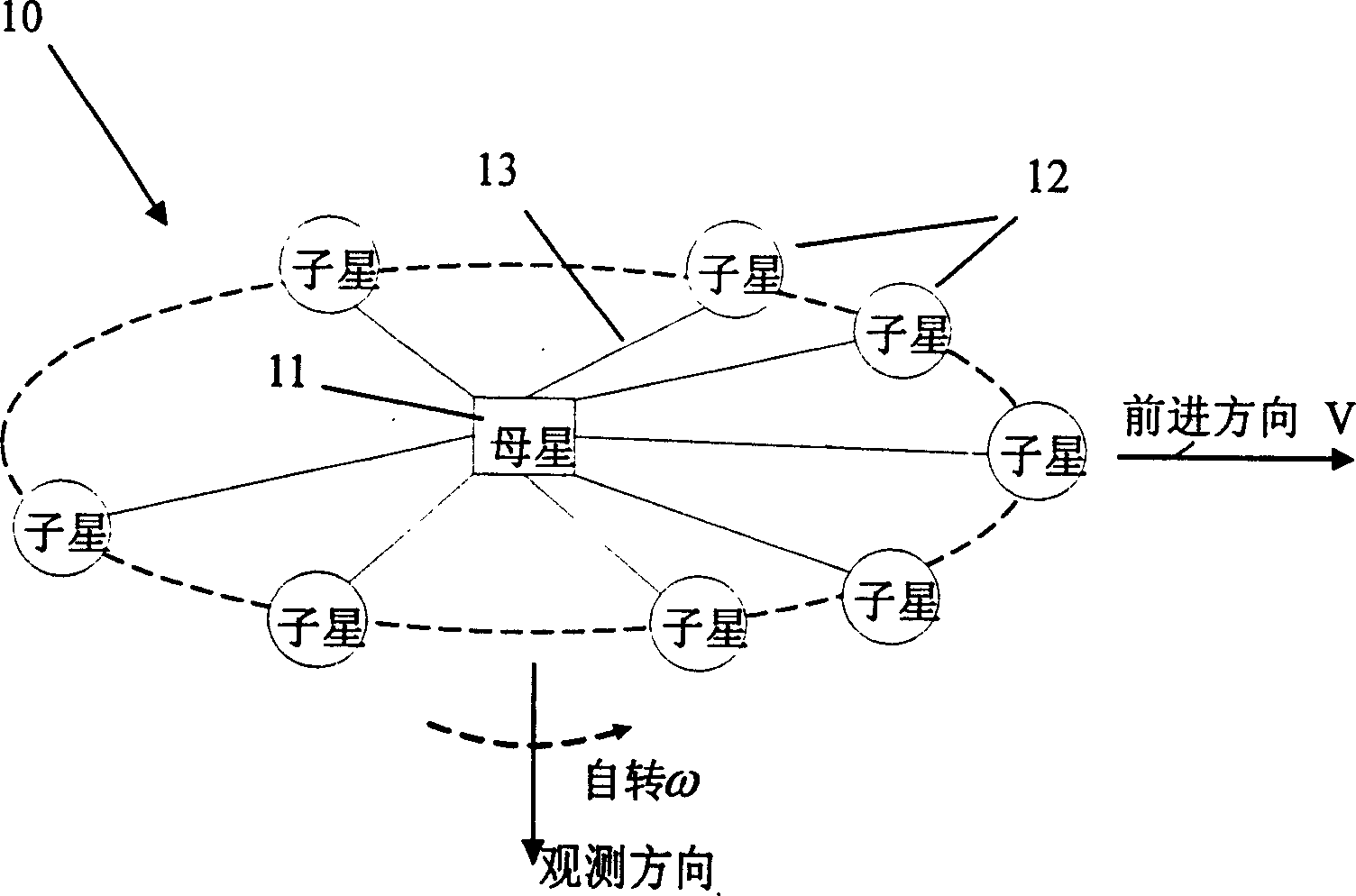
[0045] Such as figure 2 As shown, the number 10 indicates that according to the present embodiment of the present invention, the rotating scanning passive microwave imaging sub-satellite system is composed of 1 parent star 11 and 8 sub-stars 12, and 8 sub-stars 12 are not equidistantly distributed in a On the circle with the parent star 11 as the center, the spacing distribution bet...

Embodiment 2

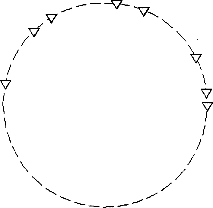
[0066] As shown in Fig. 5(a), according to the distribution of the 8 sub-stars of the present invention, the lengths of these baselines are still substantially uniformly distributed from short to long, as shown in Fig. 5(b). The difference from Example 1 is that the 8 sub-stars are not distributed on the circumference. The circle in Fig. 5(a) represents the circle with the parent star as the center, and the triangle represents the sub-stars. Others are with embodiment 1.


PUM


Abstract

The present invention discloses a kind of primary and secondary satellite system with high spatial resolution and realized by means of combining interference type synthetic aperture imaging technology and antenna array rotating scan technology. The satellite system includes one primary satellite and N secondary satellites, which has position distribution relative to the primary satellite obtained by means of spatial frequency sample base line length optimizing process. The present invention has raised aperture rarefying efficiency, simplified radiation imaging instrument system, raised spatial frequency domain coverage, raised spatial resolution, stabilized combined centrifugal force and gravitational force gradient and simplified secondary satellite posture stability control.

Description

technical field [0001] The invention mainly relates to a passive microwave imager in the field of aerospace remote sensing, and in particular to a mother-child satellite system which realizes high spatial resolution by combining an interferometric synthetic aperture imaging technology with antenna array rotation scanning. Background technique [0002] Microwave remote sensing technology is a new scientific and technological field developed after the 1960s, and it is another effective means of earth observation after visible light and infrared remote sensing. It occupies an increasingly important position in the field of remote sensing technology, and has been widely used in global change monitoring, space detection, resource development, environmental protection, and other civilian and military fields. [0003] Microwave remote sensing includes active microwave remote sensing and passive microwave remote sensing. Active remote sensing, also known as active remote sensing, o...

Claims


Application Information

Patent Timeline
Patent Type & Authority Applications(China)
IPC IPC(8): G01S13/90G01S13/89
Inventor 吴季刘浩何宝宇孙伟英
Owner NAT SPACE SCI CENT CAS
Learn More