Image forming device and controlling method thereof

A control method and image technology, applied in the direction of electrical recording technology using charge graphics, equipment and instruments using electrical recording technology using charge graphics, to achieve the effect of improving durability

Inactive Publication Date: 2006-05-10
COPYER
View PDF0 Cites 5 Cited by
  • Summary
  • Abstract
  • Description
  • Claims
  • Application Information

AI Technical Summary

Problems solved by technology

[0009] Therefore, an object of the present invention is to provide an image forming apparatus and a control method thereof, the image forming apparatus is equipped with a fixing device that prevents the lubricant from overflowing and does not deteriorate the sliding properties of the fixing film and the heating body, There is no problem of paper feeding failure, sliding sound, or poor fixing, and has excellent durability

Method used


Image

  • Image forming device and controlling method thereof
  • Image forming device and controlling method thereof
  • Image forming device and controlling method thereof

Examples


no. 1 example

[0026] Figure 4 The schematic structure of the fixing device in the image forming apparatus of this embodiment is shown, Figure 5 A portion of the device is shown enlarged.

[0027] In this fixing device, a fixing film 4 as an example of a heat-conducting rotor is used, and a ceramic heater 1 as a heating element is embedded in a film guide 2 as a supporting member. The ceramic heater 1 is contacted and supported by the heater attachment surface 3 of the film guide device 2 .

[0028] In this embodiment, on an alumina substrate with a total length of 270mm, a width of 7.8mm, and a thickness of 1.0mm, the silver-palladium resistance heating element is printed in such a way that it becomes 24Ω in the center of the length direction to form a ceramic heating element of 219mm. Device 1. The inner diameter of the endless belt-shaped fixing film 4 heated by the ceramic heater 1 is 24mm, and the base material thickness of polyimide is about 40 μm, and an adhesive layer of about 5...

no. 2 approach

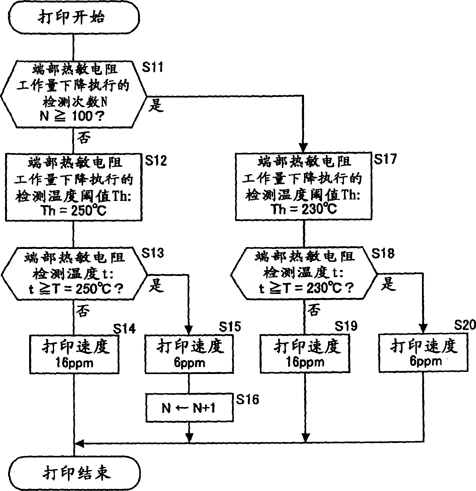
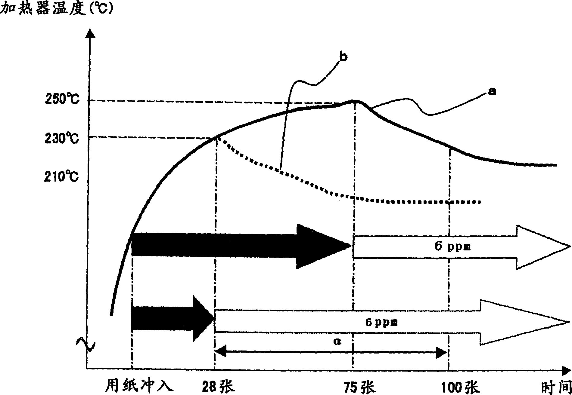
[0046] Since the outline of the fixing device is the same as that of the aforementioned first embodiment, description thereof will be omitted. Figure 7 The flow chart of is schematically showing the control procedure of the image forming apparatus in this embodiment. In addition, Table 2 shows the relationship between the paper passing ratio of the small-sized recording material and the threshold temperature Th at which the thermistor provided at the end lowers the throughput.

[0047] Small size through paper ratio Ax

End of the drop in throughput

Thermistor detection temperature threshold

Ax≥50%

230℃

Ax<50%

250℃

[0048] exist Figure 7 In the process of , when the image forming apparatus main body receives a print signal, it starts a print operation. A unit that detects the length of the recording material P in the width direction, such as a size detection sensor provided in a main body ribbon cassette not shown, dete...


PUM


Abstract

The detected temperature t at the end in the longitudinal direction of the heating body is compared with the threshold value Th, and the printing speed (throughput) is controlled based on the comparison result. The threshold Th is switched according to a predetermined condition. For example, it is used as the above-mentioned predetermined condition that the number of throughput reduction executions for which the printing speed reduction switching has been performed reaches a predetermined value. Alternatively, whether or not the small-size passing paper ratio is greater than a predetermined value is used as the above-mentioned predetermined condition. This prevents the lubricant from overflowing, prevents the sliding properties of the fixing film and the heating body from deteriorating, prevents the paper from being unable to be conveyed, generates sliding noise, and causes poor fixing, thereby improving the durability of the fixing device.

Description

technical field [0001] The present invention relates to an image forming apparatus having a fixing device for heat-fixing an unfixed image on a recording material (recording paper) used in an image forming apparatus such as a copier, a printer, a facsimile, and a control method thereof. Background technique [0002] Conventionally, in the known image forming apparatus, the toner image formed in the electrophotographic image forming part is transferred onto the recording paper, and then the recording paper is conveyed to the fixing device, and then the unfixed toner is fixed. The recording paper with the image ejected out of the device. [0003] In such an image forming apparatus, a continuous belt-shaped fixing film is brought into contact with a heating body fixed on a supporting member, and a recording material such as recording paper is brought into contact with the fixing film, and pressure is applied from thereon using a pressing member. The pressing member moves the r...

Claims


Application Information

Patent Timeline
Patent Type & Authority Applications(China)
IPC IPC(8): G03G15/20G03G21/14G03G21/20
CPCG03G2215/00599G03G15/2046G03G2215/2035G03G2215/2045
Inventor 西山隆治
Owner COPYER
Why Eureka
Try Eureka