Light mixing member, multiple-lamp lighting equipment and projection video display
A lighting device and video display technology, applied in projection devices, optics, instruments, etc., can solve the problems of uneven brightness, deterioration of displayed video varieties, and uneven color.
- Summary
- Abstract
- Description
- Claims
- Application Information
AI Technical Summary
Problems solved by technology
Method used
Image
Examples
Embodiment approach 1
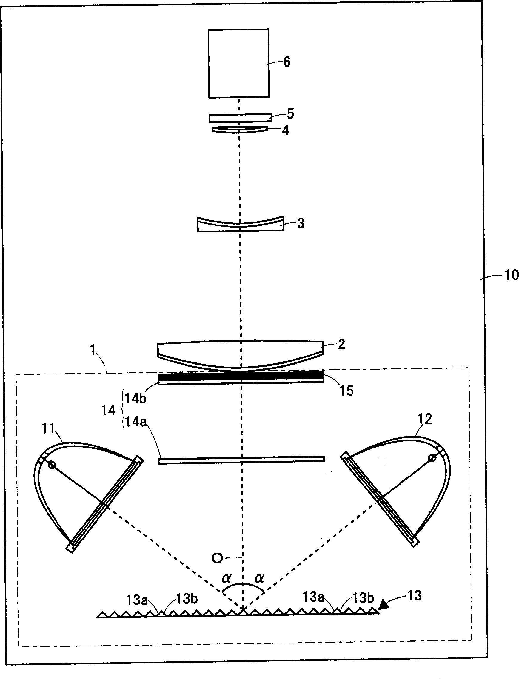
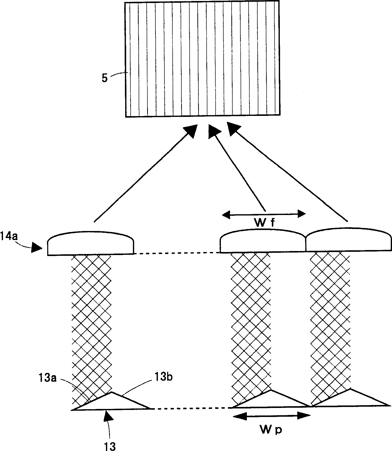
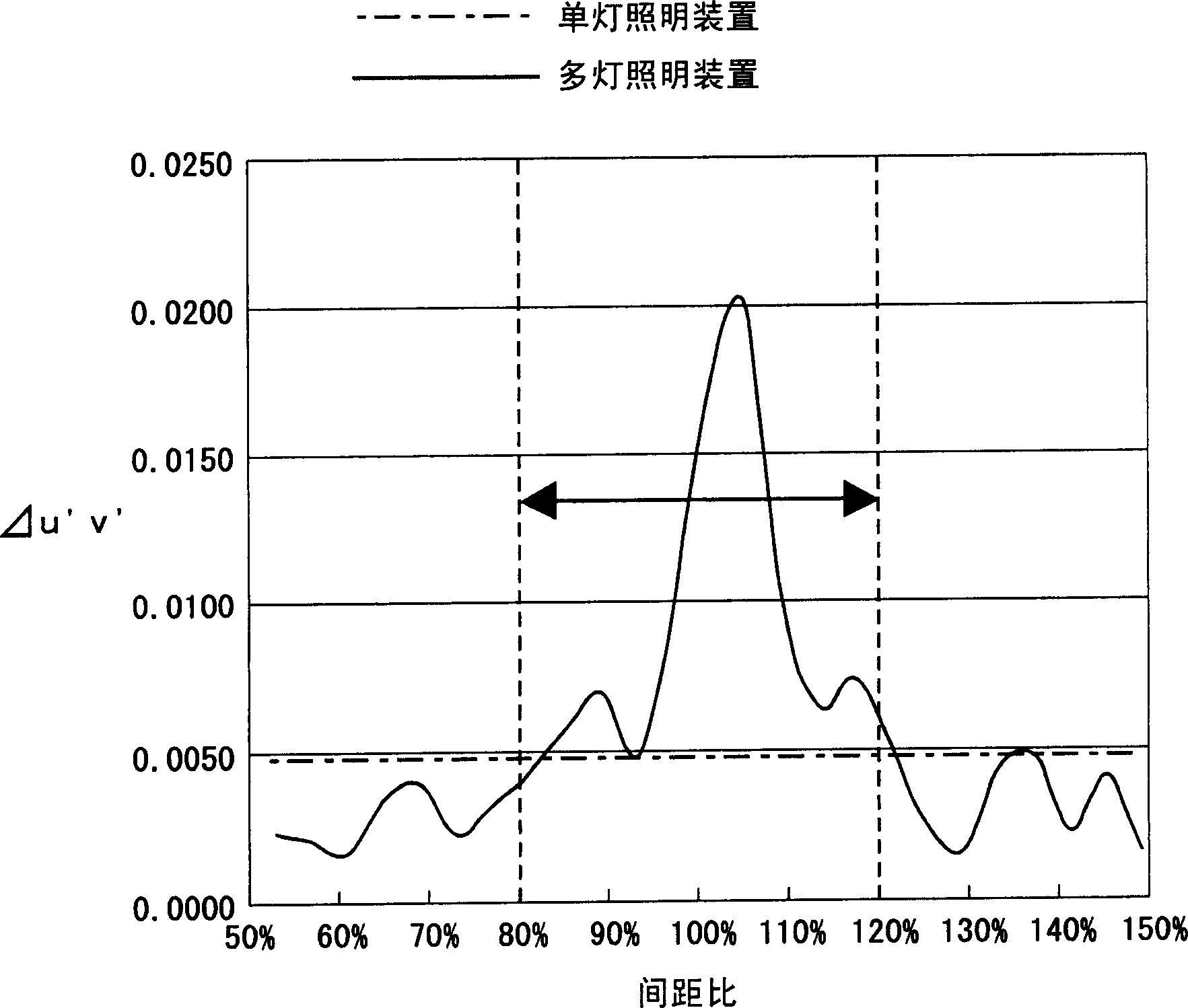
[0027] Compare below Figure 1 to Figure 3 , the multi-lamp lighting device and the projection video display device according to Embodiment 1 of the present invention will be described.
[0028] figure 1 It is a schematic configuration diagram illustrating a multi-lamp type lighting device and a projection type video display device according to an embodiment of the present invention. The multi-lamp illuminating device and the projection type video display device of this embodiment are basically the same as those disclosed in Japanese Unexamined Patent Application Publication No. 2002-296679 described in the background art. The multi-lamp lighting device 1 includes a first light source 11 , a second light source 12 , a reflective mixing member 13 , an integrator lens (fly-eye lens pair) 14 , and a polarization conversion device 15 . The projection type video display device 10 includes the above-mentioned multi-lamp type lighting device 1 , condenser lenses 2 , 3 , 4 , a liqu...
Embodiment approach 2
[0041] Compare below Figure 4 and Figure 5 , the light mixing member (reflection mixing member), multi-lamp lighting device, and projection video display device according to Embodiment 2 of the present invention will be described. In addition, the basic configurations of the multi-lamp type lighting device and the projection type video display device are the same as those of Embodiment 1, so they are also compared. figure 1 Be explained.
[0042] reflective mixing components 13', such as Figure 4 As shown in the plan view of (a) and the side view of (b), there are area A and area B. That is to say, it is divided into two areas A and B with the line perpendicular to the corrugated lines of the three corrugated column parts as the boundary, and the two areas A and B are staggered with each other at a distance of 1 / 2 of the corrugated line pitch of the three corrugated column parts. In this way, each area A, B is composed of two reflective optical members (hereinafter, th...
PUM
 Abstract
Description
Claims
Application Information
 - R&D Engineer
- R&D Manager
- IP Professional
- Industry Leading Data Capabilities
- Powerful AI technology
- Patent DNA Extraction
Browse by: Latest US Patents, China's latest patents, Technical Efficacy Thesaurus, Application Domain, Technology Topic, Popular Technical Reports.
© 2024 PatSnap. All rights reserved.Legal|Privacy policy|Modern Slavery Act Transparency Statement|Sitemap|About US| Contact US: help@patsnap.com


