Light mixing member, multiple-lamp lighting equipment and projection video display

A lighting device and video display technology, applied in projection devices, optics, instruments, etc., can solve problems such as uneven color, poor brightness distribution, and deterioration of display video varieties

Inactive Publication Date: 2009-07-29
SANYO ELECTRIC CO LTD
View PDF5 Cites 0 Cited by
  • Summary
  • Abstract
  • Description
  • Claims
  • Application Information

AI Technical Summary

Problems solved by technology

Uneven brightness or uneven color occurs in the projected video projected on the screen due to poor brightness distribution in each color
Human eyes are more likely to perceive color unevenness than brightness unevenness, so this color unevenness causes a large deterioration in the variety of displayed video

Method used


Image

  • Light mixing member, multiple-lamp lighting equipment and projection video display
  • Light mixing member, multiple-lamp lighting equipment and projection video display
  • Light mixing member, multiple-lamp lighting equipment and projection video display

Examples


Embodiment approach 1

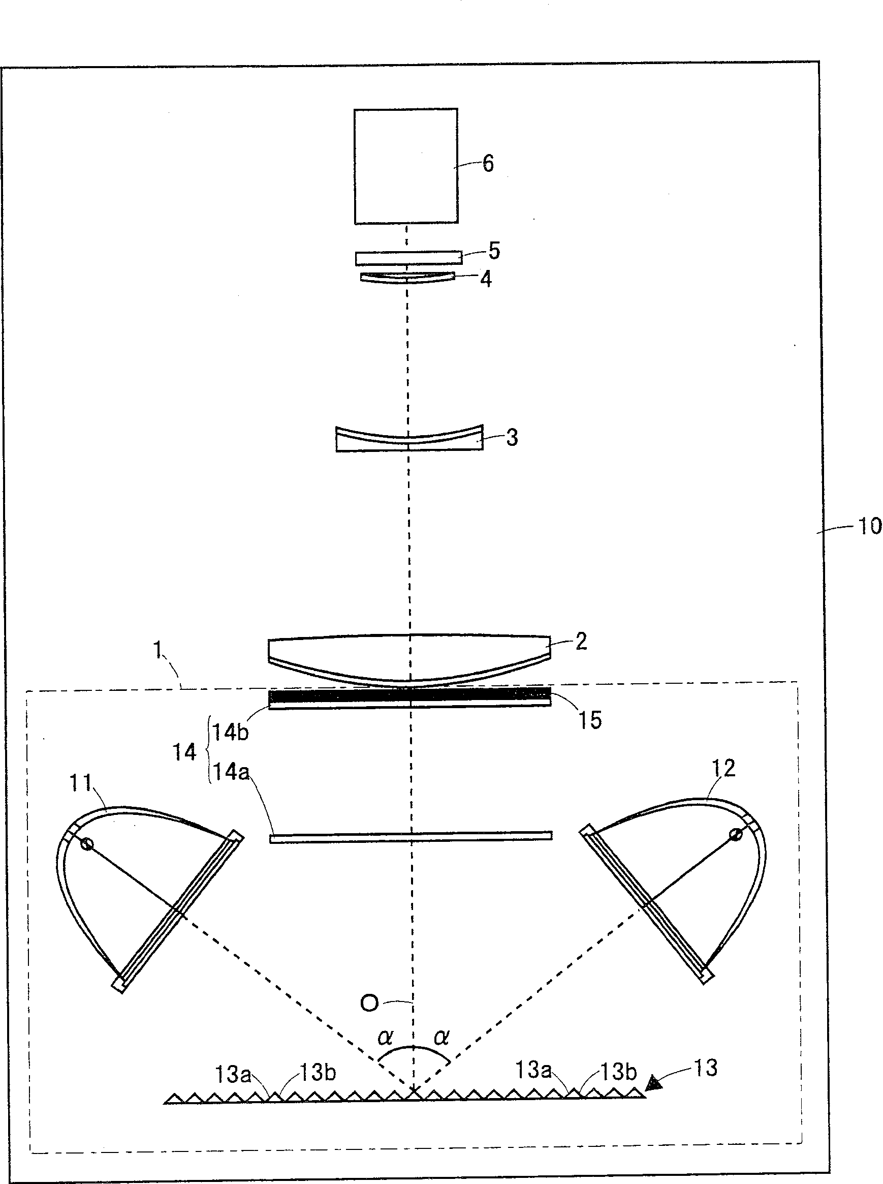
[0027] Compare below Figure 1 to Figure 3 , the multi-lamp lighting device and the projection video display device according to Embodiment 1 of the present invention will be described.

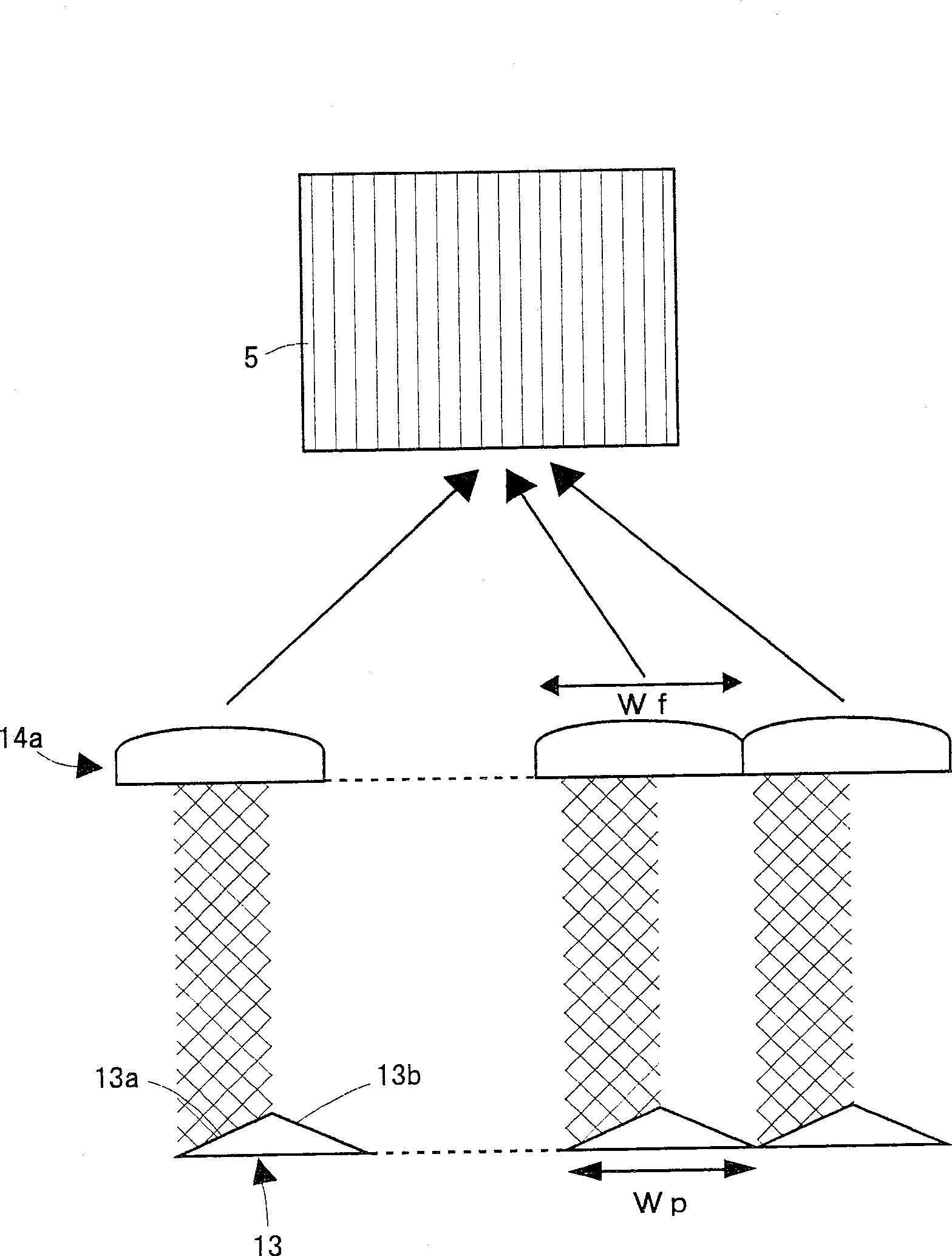
[0028] figure 1 It is a schematic configuration diagram illustrating a multi-lamp type lighting device and a projection type video display device according to an embodiment of the present invention. The multi-lamp type lighting device and the projection type video display device of this embodiment are basically the same as those disclosed in JP-A-2002-296679 described in the background art. The multi-lamp lighting device 1 includes a first light source 11 , a second light source 12 , a reflective mixing member 13 , an integrating lens (fly-eye lens pair) 14 , and a polarization conversion device 15 . The projection type video display device 10 includes the above-mentioned multi-lamp type lighting device 1 , condenser lenses 2 , 3 , 4 , a liquid crystal display panel 5 , and a projection le...

Embodiment approach 2

[0041] Compare below Figure 4 and Figure 5 , the light mixing member (reflection mixing member), multi-lamp lighting device, and projection video display device according to Embodiment 2 of the present invention will be described. In addition, the basic configurations of the multi-lamp type lighting device and the projection type video display device are the same as those of Embodiment 1, so they are also compared. figure 1 Be explained.

[0042] reflective mixing components 13', such as Figure 4 As shown in the plan view of (a) and the side view of (b), there are area A and area B. That is to say, it is divided into two regions A and B by a line perpendicular to the corrugated lines of the triangular prism part, and the two regions A and B are staggered from each other at a distance of 1 / 2 of the pitch of the corrugated lines of the triangular prism part. In this way, each area A, B is composed of two reflective optical members (hereinafter, the reflective optical mem...


PUM


Abstract

The light from the first light source is incident on the reflective surface (13a) of the reflective mixing member (13), and the light from the second light source is incident on the reflective surface (13b). The relationship between the spacing Wp between the part (three corrugated column parts) formed by the reflection surface (13a) and the reflection surface (13b) in the reflection mixing part (13) and the lens spacing Wf is: (Wp / Wf≠1 ). Therefore, light beams with different distributions are incident on each lens portion of the fly-eye lens (14a), thereby preventing uneven brightness of the light incident on the liquid crystal display panel (5), and simultaneously preventing color unevenness on the screen.

Description

technical field [0001] The invention relates to a light mixing component, a multi-lamp illuminating device and a projection type video display device. Background technique [0002] Conventionally, as a device for displaying a large screen, a liquid crystal projector is known that irradiates light from a lighting device onto a liquid crystal panel, and enlarges and projects the image displayed on the liquid crystal panel onto a screen. A number of brilliant multi-lamp lighting devices (exhibited in Tezuo Bulletin No. 2002-296679). Such as Figure 9 As shown, the multi-lamp illuminating device 50 synthesizes the light beams emitted by the first light source 51 and the second light source 52 by the reflective mixing member 53 . The above-mentioned reflective mixing component 53, such as Figure 7 As shown, there are alternate first reflective surfaces 53a and second reflective surfaces 53b. The reflective mixing element 53 is also referred to as a prism array. The related m...

Claims


Application Information

Patent Timeline
Patent Type & Authority Patents(China)
IPC IPC(8): G03B21/00
Inventor 池田贵司黑坂刚孝金山秀行石井孝治
Owner SANYO ELECTRIC CO LTD
Why Eureka
Try Eureka