Visible image monitoring method for protecting privacy right and its system
A privacy and image technology, applied in closed-circuit television systems, analog security/charging systems, etc., can solve problems such as blurring of privacy rights and images, and achieve the effect of solving protection problems.
- Summary
- Abstract
- Description
- Claims
- Application Information
AI Technical Summary
Problems solved by technology
Method used
Image


Examples
Embodiment 1
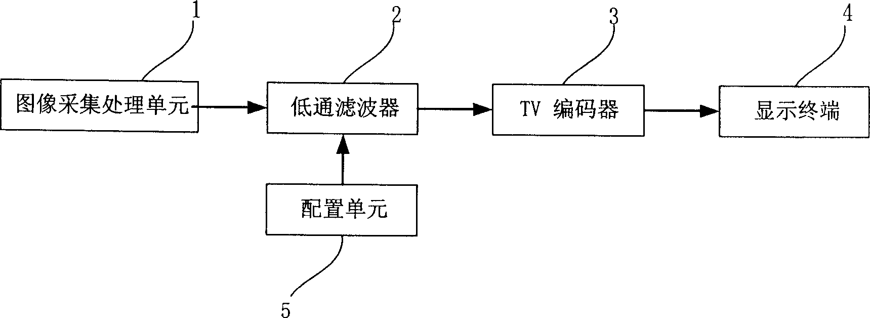
[0031] refer to figure 1 As shown, the visual image monitoring system for protecting the right of privacy in this embodiment is used to monitor the situation of passengers getting on and off at the back door of the bus. It includes an image acquisition processing unit 1 , a low-pass filter 2 , a TV encoder 3 and a display terminal 4 connected in sequence, and a configuration unit 5 is connected to the low-pass filter 2 . Compared with the existing vehicle monitoring system, a low-pass filter 2 and a configuration unit 5 are added.
[0032] The image acquisition and processing unit 1 is a camera, which is generally installed on the ceiling near the rear door in the compartment, and is used to collect the images on the scene and convert them into digital signals, and then send them to a low-pass filter 2, which is controlled by the low-pass filter 2 The image signal is blurred and then output to the TV encoder 3. The TV encoder 3 converts the received blurred image signal into ...
Embodiment 2
[0037] The privacy-protecting visual image monitoring system in this embodiment is used to directly blur images during on-site interviews. Such as figure 2 As shown, the system includes an image acquisition processing unit 1 , a face recognition unit 7 , a face blur processing unit 8 , a TV encoder 3 and a display terminal 4 connected in sequence, and the memory 6 is connected to the face blur processing unit 8 .
[0038] The image acquisition processing unit 1 is a camera, and the output is a digital signal. The face recognition unit 7 recognizes the image from the camera, and various recognition methods can be used. The requirements for recognition accuracy are not high here; the face recognition unit 7 completes After the recognition, the recognized face area and the captured original image are sent to the face blur processing unit 8, and the face blur processing unit 8 replaces the image in the face area with a mosaic. Specifically, the The grayscale signal in the area r...
Embodiment 3
[0042] The privacy-protecting visual image monitoring system in this embodiment is used in a family monitoring system, can be accessed through the network, and different users can see images with different blur levels. Such as image 3 As shown, the system includes an image acquisition processing unit 1 , an image blurring processing unit 9 , a first communication interface unit 10 , a first line 11 and a first monitoring terminal 12 connected in sequence. In addition, the image blur processing unit 9 is also connected with the second communication interface unit 10', the second line 11' and the second monitoring terminal 12'. In addition, there is an access control unit 13 connected with the image blur processing unit 9 and each communication interface unit. There can be more than 2 groups of communication interface units, lines and monitoring terminals. The line can be in various forms such as the Internet, the line of the community monitoring system, or the wireless commu...
PUM
 Abstract
Description
Claims
Application Information
 - R&D
- Intellectual Property
- Life Sciences
- Materials
- Tech Scout
- Unparalleled Data Quality
- Higher Quality Content
- 60% Fewer Hallucinations
Browse by: Latest US Patents, China's latest patents, Technical Efficacy Thesaurus, Application Domain, Technology Topic, Popular Technical Reports.
© 2025 PatSnap. All rights reserved.Legal|Privacy policy|Modern Slavery Act Transparency Statement|Sitemap|About US| Contact US: help@patsnap.com