Noise reducing apparatus of linear compressor

A linear compressor, noise technology, applied in mechanical equipment, machines/engines, liquid variable capacity machinery, etc., can solve the problem of ineffective reduction, affecting suction efficiency, inconsistency, etc., to reduce suction noise and improve suction. The effect of efficiency

Inactive Publication Date: 2006-05-03
LG ELECTRONICS (TIANJIN) APPLIANCES CO LTD
View PDF0 Cites 0 Cited by
  • Summary
  • Abstract
  • Description
  • Claims
  • Application Information

AI Technical Summary

Problems solved by technology

Ineffective at reducing noise in a variety of frequency ranges generated when fluid is sucked in
And because an insertion tube 9 is located at the center of the piston 30, it is inconsistent with the eccentric suction port 34, which affects the suction efficiency

Method used


Image

  • Noise reducing apparatus of linear compressor
  • Noise reducing apparatus of linear compressor
  • Noise reducing apparatus of linear compressor

Examples


Embodiment Construction

[0035] Below in conjunction with accompanying drawing and specific embodiment the present invention is described in further detail:

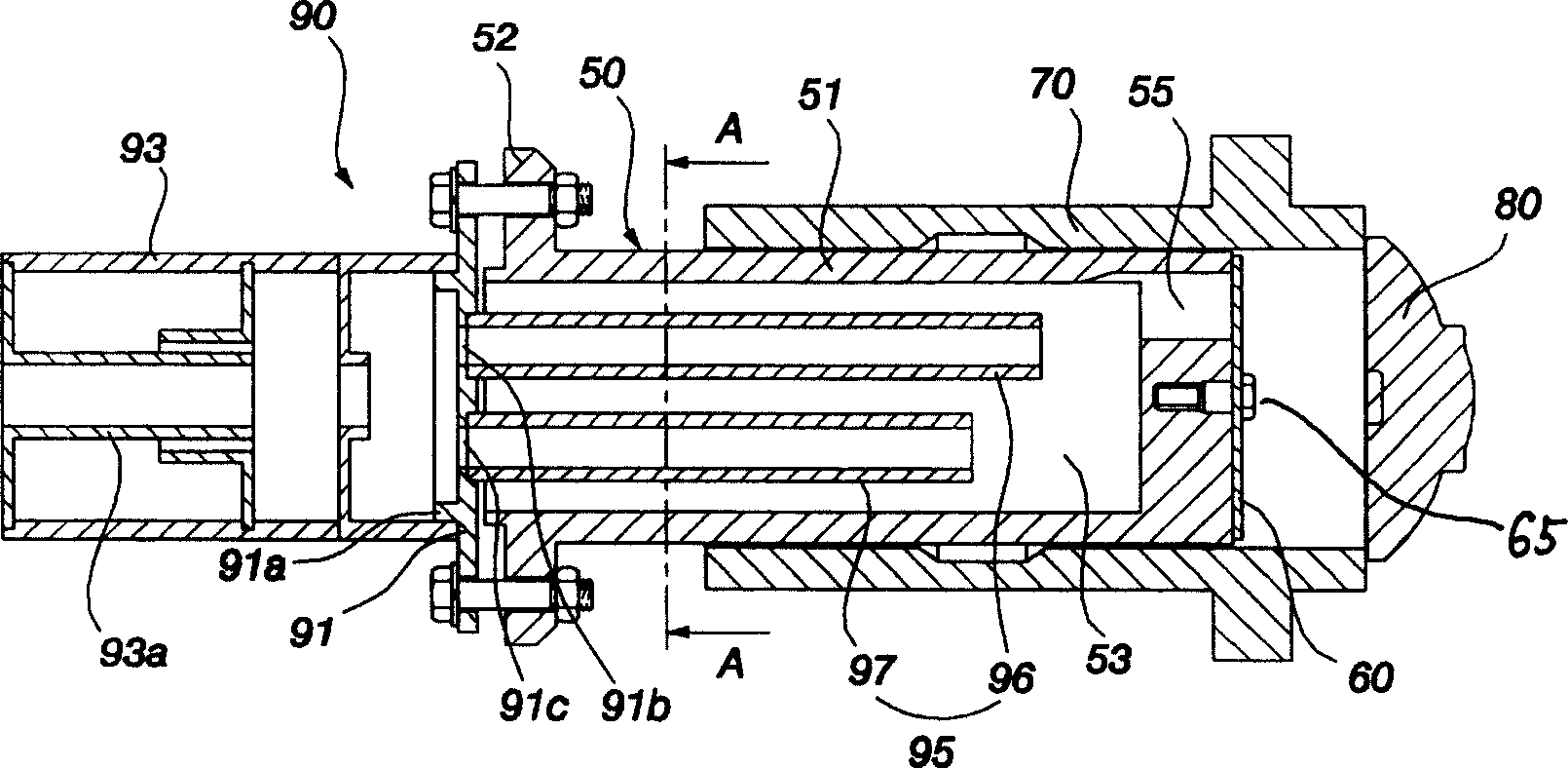
[0036] Such as image 3 As shown, the noise reduction device of the linear compressor of the present invention is provided with a muffler 90 on the rear side of the piston 50 .

[0037] The piston 50 is composed of a body part 51 and a flange part 52. The body part 51 is cylindrical and moves linearly inside the cylinder 70; the flange part 52 is fixed on the magnet frame (not shown in the figure). A suction flow path 53 is formed inside the main body portion 51 , and a suction port 55 is formed in a closed front portion.

[0038] A suction valve 60 that opens and closes the suction port 55 is provided on the front side of the piston 50 . The suction valve 60 is fixed to the front central portion of the piston 50 by a connecting member such as a screw 65 .

[0039] 80 is a discharge valve 80 for opening and closing the compression chamber of ...


PUM


Abstract

The invention discloses a noise reduction device of linear compressor, which is characterized by the following: multiple insert pipes of different lengths are set behind the piston in connection with the suction flow path of piston; the suction inlet is formed in front of the piston. The longer insert pipe is set near the suction inlet, which improves the suction efficiency.

Description

technical field [0001] The invention relates to a linear compressor, in particular to a noise reduction device for a linear compressor that reduces suction noise by using two suction pipes with different lengths. Background technique [0002] Generally speaking, the linear compressor (Linear compressor) utilizes the linear driving force of the linear motor, and the piston inhales and compresses the fluid and then discharges it while performing linear reciprocating motion inside the cylinder. [0003] Such as figure 1 As shown, in the conventional linear compressor, a cylinder block 12 having a cylinder 13 and a rear cover 15 having a fluid suction pipe 16 are provided inside a closed container 10 . The cylinder block 12 and the rear cover 15 are cushionably supported inside the airtight container 10 via the first damper 17 and the second damper 18 . [0004] A linear motor 20 that generates a driving force for compressing fluid is provided between the cylinder block 12 and...

Claims


Application Information

Patent Timeline
IPC IPC(8): F04B39/00F04B35/04
Inventor 朴景培崔基喆洪彦杓郭泰熹奇成铉许锺泰金镛洙
Owner LG ELECTRONICS (TIANJIN) APPLIANCES CO LTD
Why Eureka
Try Eureka