Ultrafiltration membrane and preparation method thereof
A technology of ultrafiltration membrane and filter layer, applied in ultrafiltration, chemical instruments and methods, membranes, etc., can solve the problems of production efficiency decline, easy deformation, easy wrinkling, etc.
- Summary
- Abstract
- Description
- Claims
- Application Information
AI Technical Summary
Problems solved by technology
Method used
Image
Examples
Embodiment 1
[0116] Solutions were prepared in the examples as follows.
[0117] Polyethersulfone (PES) membranes were cast from solutions containing polymer polyethersulfone (PES), Radel A200 resin (Solvay) solvent, N-methylpyrrolidone (NMP) and non-solvent triethylene glycol (TEG). The solution was homogeneous at room temperature but phase separated when heated. The temperature at which a solution begins to phase separate is called the cloud point temperature, which is a function of the solution composition and is extremely sensitive to the concentration of water. It is important to avoid exposing the raw materials, especially TEG, and the final solution to the atmosphere as much as possible. The polymer should be pre-dried eg at 150° C. for 3 hours.
[0118] Mixing is carried out in two steps. First, the polymer was added to a mixture of all NMP and only part of TEG. The portions were mixed while heating to about 50°C to 80°C until the solution was clear. Reduce the temperature to ...
Embodiment 2
[0129] A first polymer solution was prepared by dissolving 22% PES (Radel A200 resin) in 28.1% NMP and 49.9% TEG. The cloud point was measured to be 48.6°C.
[0130] A second polymer solution was prepared by dissolving 14% PES (Radel A200 resin) in 29.2% NMP and 56.8% TEG. An additional 3% of NMP was added to reach a cloud point of 59.3°C.
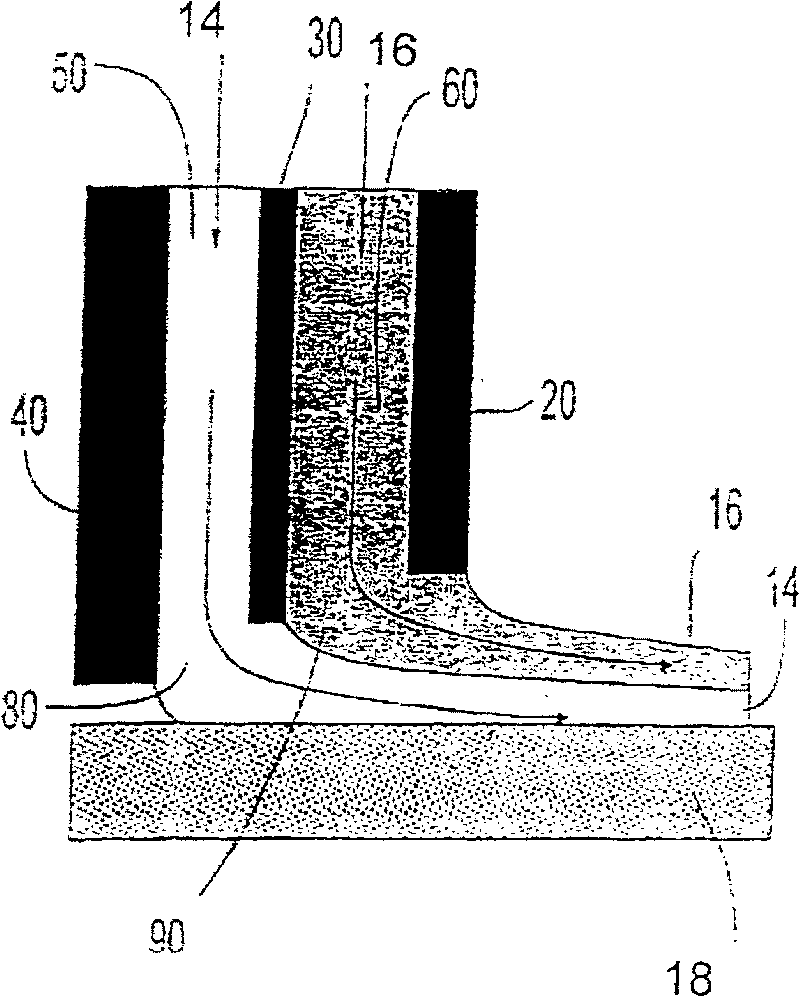
[0131] The two solutions were co-cast as described in Example 1. The casting thickness of the first solution was adjusted to a final layer thickness of 140 microns. The cast thickness of the second solution was adjusted to a final layer thickness of 13 microns or about 8% of the total film thickness.
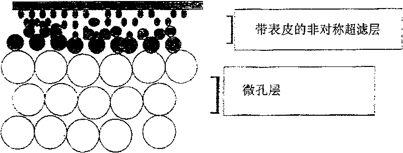
[0132] The formation conditions were chosen such that the first solution was quickly exposed to a drum heated to 55°C, above its cloud point, before being immersed in a water bath at 45°C. The results showed that a macroporous-free ultrafiltration layer was formed from the first polymer solution and a thin microporous layer was formed fr...
Embodiment 3
[0136] A first polymer solution was prepared by dissolving 17% PES (Radel A200) in 29.2% NMP and 53.8% TEG. The cloud point can be measured to be 43°C. This will be the bottom or support microporous layer.
[0137] A second polymer solution was prepared by dissolving 21% PES (Radel A200) in 37% NMP and 42% TEG. The cloud point is above 150°C and cannot be measured. This will be the top UF layer.
[0138] The two solutions were co-cast as described in WO 01 / 89673 (Kools). The second solution forms a layer on the first solution. The cast thickness of the first solution was adjusted to a final microporous membrane layer thickness of 160 microns. The cast thickness of the second solution was about 30 microns or about 20% of the total film thickness.
[0139] The forming conditions were chosen such that the layered solution was heated rapidly on the casting drum to within the vicinity of its cloud point before being immersed in a water bath at 55°C. The second solution has n...
PUM
 Abstract
Description
Claims
Application Information
 - R&D
- Intellectual Property
- Life Sciences
- Materials
- Tech Scout
- Unparalleled Data Quality
- Higher Quality Content
- 60% Fewer Hallucinations
Browse by: Latest US Patents, China's latest patents, Technical Efficacy Thesaurus, Application Domain, Technology Topic, Popular Technical Reports.
© 2025 PatSnap. All rights reserved.Legal|Privacy policy|Modern Slavery Act Transparency Statement|Sitemap|About US| Contact US: help@patsnap.com


