
Vertical take-off and landing aircraft

A vertical take-off and landing aircraft and airframe technology, applied in the field of aircraft, can solve problems such as low reliability, impact on flight safety, complex airframe, etc., and achieve the effects of reducing the number of engines, improving safety performance, and good flightworthiness

Inactive Publication Date: 2006-04-05
李环
View PDF1 Cites 25 Cited by
  • Summary
  • Abstract
  • Description
  • Claims
  • Application Information

AI Technical Summary

Problems solved by technology

The V-22 uses a pair of tilt rotors mounted on the end of the main wing, which is not stable enough for vertical take-off and landing
Page 16 of the 6th issue of "Aviation Knowledge" magazine in 2002 reported the V-44 tilt-rotor aircraft concept. It takes off and lands vertically, but the frontal projections of the front and rear rotors overlap, causing air vibration between the front and rear rotors, making its level flight performance worse than that of conventional aircraft; moreover, it uses a large number of engines, and any engine fails during operation , will cause the power imbalance of the whole machine and affect flight safety.
Although it adopts a computer-controlled rotor coordination system, it still makes the airframe complex and the reliability is not high

Method used


Image

  • Vertical take-off and landing aircraft
  • Vertical take-off and landing aircraft
  • Vertical take-off and landing aircraft

Examples


Embodiment Construction

[0017] The present invention will be described in further detail below with reference to the specific embodiments in conjunction with the accompanying drawings.

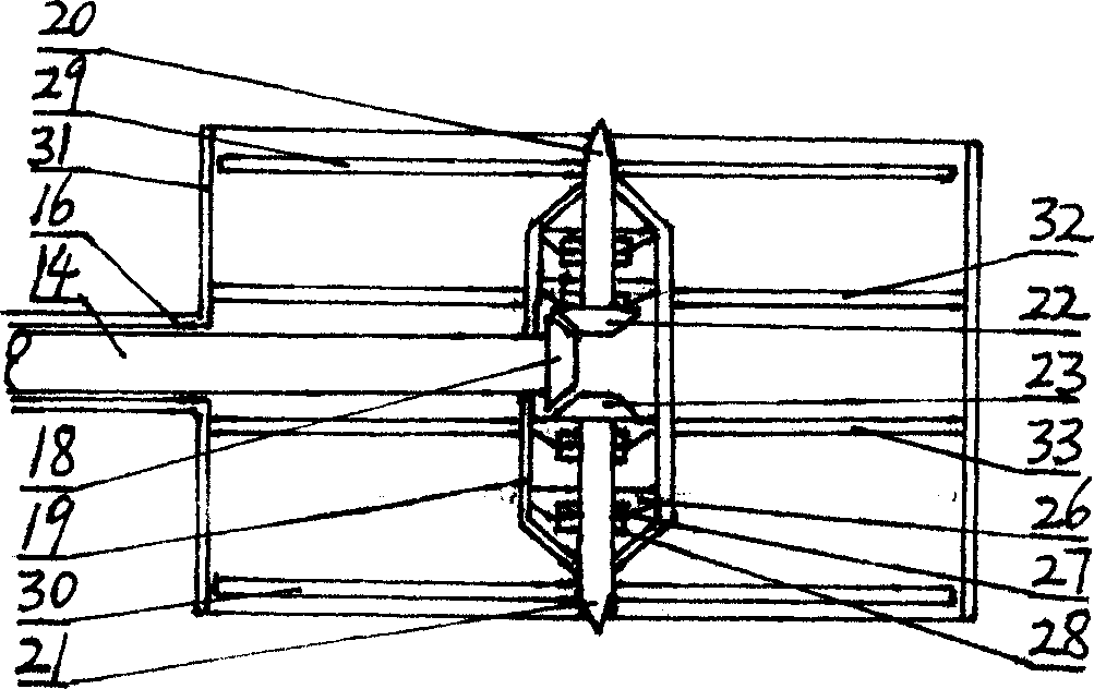
[0018] In Fig. 1: 1 is the body, 2 is the main wing, 3 is the engine, 4 is the propeller, 5 is the vertical empennage, and 6 is the horizontal empennage. The torque produced by the engine 3 installed on the body 1 or the main wing 2 is transmitted to the input shaft 10 of the clutch 9 installed in the body 1 through the transmission gear 8 (or transmission belt, chain, etc.), and the clutch 9 is engaged with the central transmission (or speed reducer). Gear) 11, the transmission (or reducer) 11 transmits the torque after torque conversion to the bevel gear 13 at the end of the transmission shaft 12 (or transmission belt, transmission chain, hydraulic transmission mechanism, etc.) The shaft ends of the drive shafts 14 of at least two pairs of propellers 4 are input on the bevel gear 15 . The drive shaft 14 is sleeved...


PUM


Abstract

This invention discloses one vertical lift plane, which relates to one aviator and to one inclined rotation fan or inclined channel fan pusher vertical plane, which comprises plane body, main wing, motor, pusher, vertical tail wing, level tail wing, lift rack and other device. The invention is characterized by the following: power from at least one motor is concentrated through central gear or decelerator through drive power system to distribute on machien gravity or main wing front and back. The left and right inclined axis end can pass level and vertical rotation to seaprte pusher front projection.

Description

technical field [0001] The invention relates to an aircraft, in particular to a vertical take-off and landing aircraft with tilting rotors or tilting ducted fan propellers. Background technique [0002] At present, there are U.S. V-22 and V-44 tilt-rotor aircraft about the invention of tilt-rotor or tilt-ducted fan propeller, and there is Chinese patent No. CN97202712.2—a vertical take-off and landing biplane. The V-22 uses a pair of tiltrotors mounted on the ends of the main wings, which are not stable enough for vertical take-off and landing. Page 16 of the 6th issue of "Aviation Knowledge" magazine in 2002 reported the V-44 tilt-rotor aircraft concept. It takes off and lands vertically, but the frontal projections of the front and rear rotors overlap, causing air vibration between the front and rear rotors, making its level flight performance worse than that of conventional aircraft; moreover, it uses a large number of engines, and any engine fails ...

Claims


Application Information

Patent Timeline
IPC IPC(8): B64C29/00
Inventor 李环
Owner 李环
Learn More