Green uninterrupted power system
A power supply and green technology, applied in the field of green uninterruptible power supply, can solve the problems of no voltage high-end compensation function, low efficiency, high failure rate, etc.
- Summary
- Abstract
- Description
- Claims
- Application Information
AI Technical Summary
Problems solved by technology
Method used
Image

Examples
Embodiment approach 1
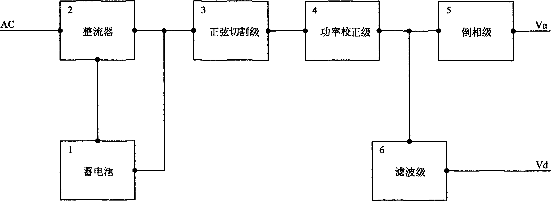
[0030] Embodiment 1: It can output both AC and DC, and the ratio of AC voltage to DC voltage can be selected by the user.
[0031] When the mains is in the normal range, the relay RL is in the normally closed contact, and the input voltage only passes through the rectifier, power correction stage and phase inverter stage. The rectifier inverts the sinusoidal AC voltage of the mains into steamed waves, which is convenient for unilateral power factor correction. The purpose of unilateral power factor correction for AC voltage is to enable AC and DC voltage to pass through the same power channel, thereby simplifying the circuit structure and saving the cost of the whole machine. After the steamed bread wave voltage after power factor correction passes through the capacitor C2, the superimposed high-frequency pulse generated by the power factor corrector is filtered out, and then the steamed bread wave voltage is restored to a sinusoidal AC output voltage by the inverter stage Va...
Embodiment approach 2
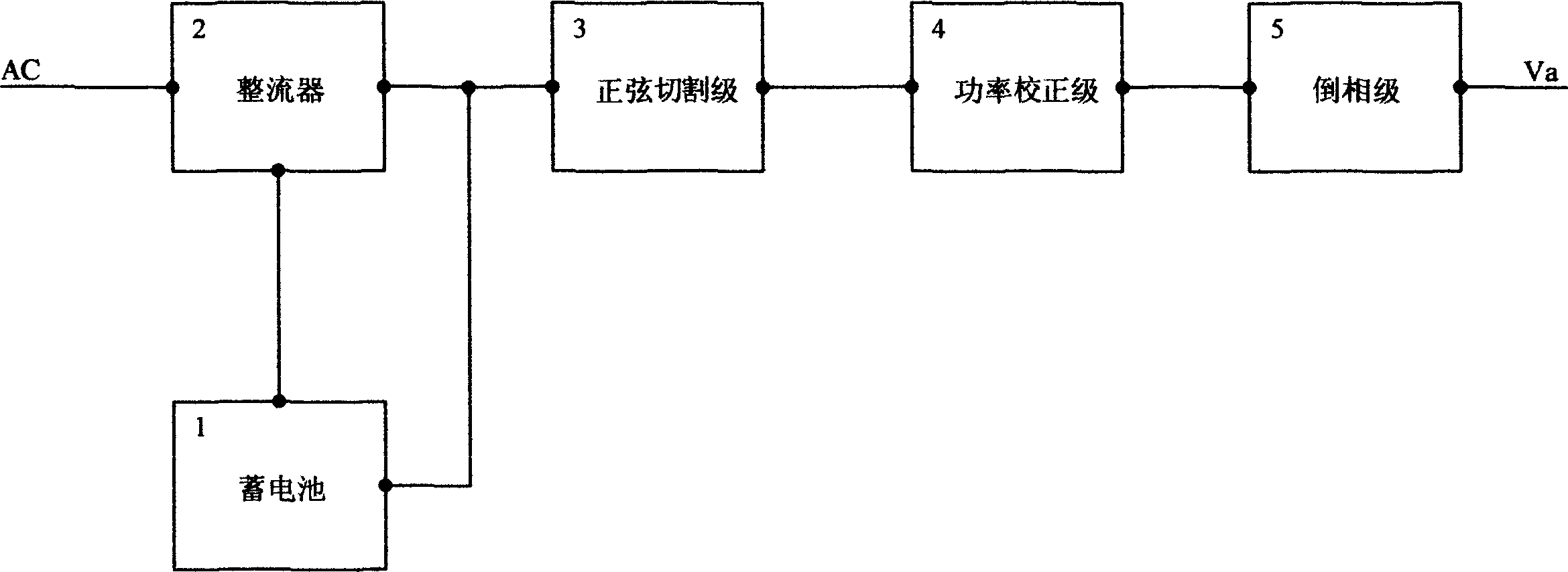
[0037] Embodiment 2: Only output AC voltage.
[0038] If only the AC voltage is output, the filter stage connected after the power correction stage in the first embodiment can be removed, and the working process and working principle are the same as those in the first embodiment.
Embodiment approach 3
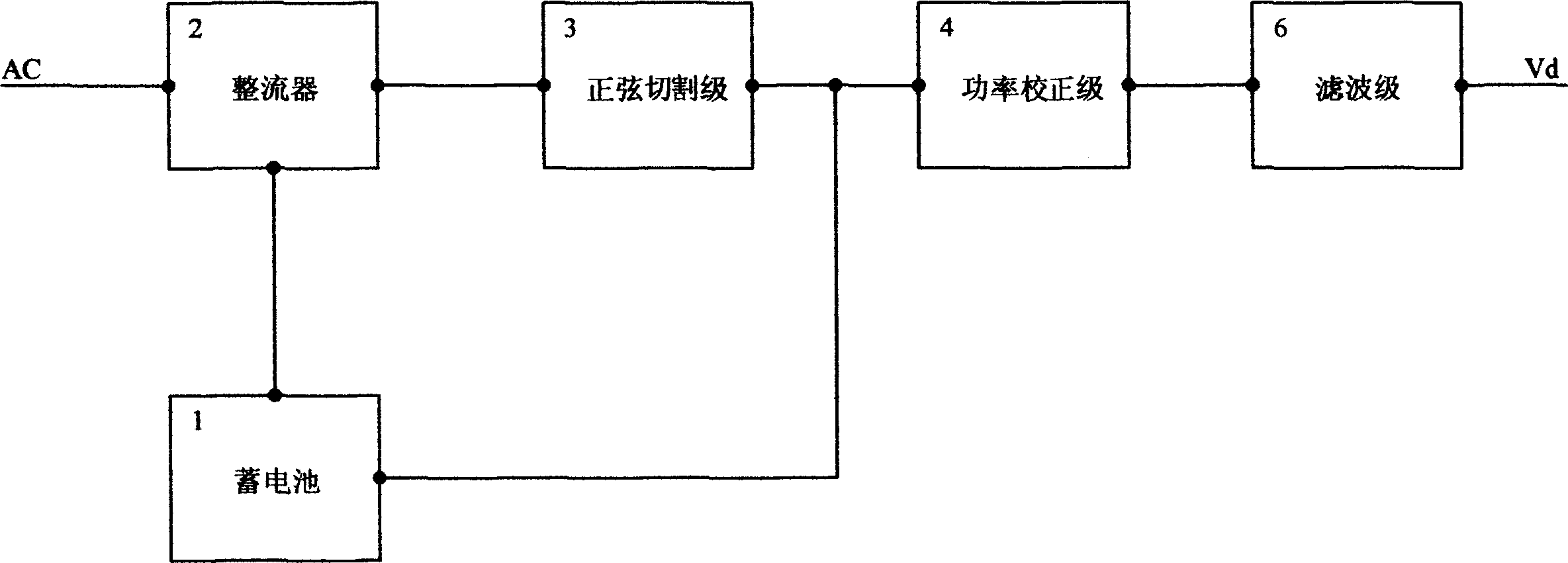
[0039] Embodiment 3: Only output DC voltage.
[0040]If only DC voltage is output, the inverter stage connected to the power correction stage in Embodiment 1 can be removed. The working process and working principle are basically the same as Embodiment 1. At this time, the battery voltage does not pass through the sine cutting stage, but directly enters the power Correction level, because the output voltage is DC, it is not necessary to cut the DC into a sine wave.
[0041] A few notes:
[0042] 1. The circuit composed of the field effect transistor Q1 in the sine cutting stage (see Figure 7 ), simple structure, less components and more functions:
[0043] 1) emitter follower,
[0044] 2) Linear DC regulator,
[0045] 3) low frequency power amplifier,
[0046] 4) High frequency power converter,
[0047] Q3, the pre-amplification stage of field effect transistor Q1, amplifies the unilateral pulsating sine wave reference signal Vsin entering from the source to the rated v...
PUM
 Abstract
Description
Claims
Application Information
 - R&D
- Intellectual Property
- Life Sciences
- Materials
- Tech Scout
- Unparalleled Data Quality
- Higher Quality Content
- 60% Fewer Hallucinations
Browse by: Latest US Patents, China's latest patents, Technical Efficacy Thesaurus, Application Domain, Technology Topic, Popular Technical Reports.
© 2025 PatSnap. All rights reserved.Legal|Privacy policy|Modern Slavery Act Transparency Statement|Sitemap|About US| Contact US: help@patsnap.com