Steering device for motor vehicle

A steering device and vehicle technology, applied in the steering column, steering control mounted on the vehicle, steering control, etc., can solve the problems of high surface pressure, uncontrollable lag amplitude, and the steering shaft cannot meet the torque transmission performance and life. , to achieve the effect of stable sliding load

Inactive Publication Date: 2006-03-08
NSK LTD +1
View PDF3 Cites 17 Cited by
  • Summary
  • Abstract
  • Description
  • Claims
  • Application Information

AI Technical Summary

Problems solved by technology

[0034] In these structures, since the leaf springs with different curvatures are arranged in the grooves of the male or female shafts with curvature, it is difficult to obtain a large deflection amount of the leaf springs
Therefore, it is difficult to provide a leaf spring having an amount of deflection that can allow fluctuations in machining accuracy of the male and female shafts
[0035] When the torque is input, the male shaft, the leaf spring, the ball and the female shaft contact each other (crowd together) to transmit the torque, so that the point of contact with the ball has a very high surface pressure, and the steering shaft may not be able to meet the needs of the vehicle Torque transmission performance and life (especially when the steering shaft is combined with column assist electric power steering that needs to transmit high torque)
[0036] Since the external leaf spring tends to slip relative to the female shaft and is prone to lag when transmitting torque, there is a structural problem of not being able to control the magnitude of this lag
[0037] However, in the above-mentioned prior art, even considering Japanese Patent Application No. 1-145670, Fig. 9 to Figure 12 The prior art shown, the above-mentioned European Patent Application Publication No. EP1078843A1 and the above-mentioned German Patent No. DE3730393C2, do not provide telescoping shafts with properties that can be combined with column-assisted electric steering
Therefore, it is difficult to obtain a steering system with excellent performance satisfying the above items

Method used


Image

  • Steering device for motor vehicle
  • Steering device for motor vehicle
  • Steering device for motor vehicle

Examples


no. 1 example

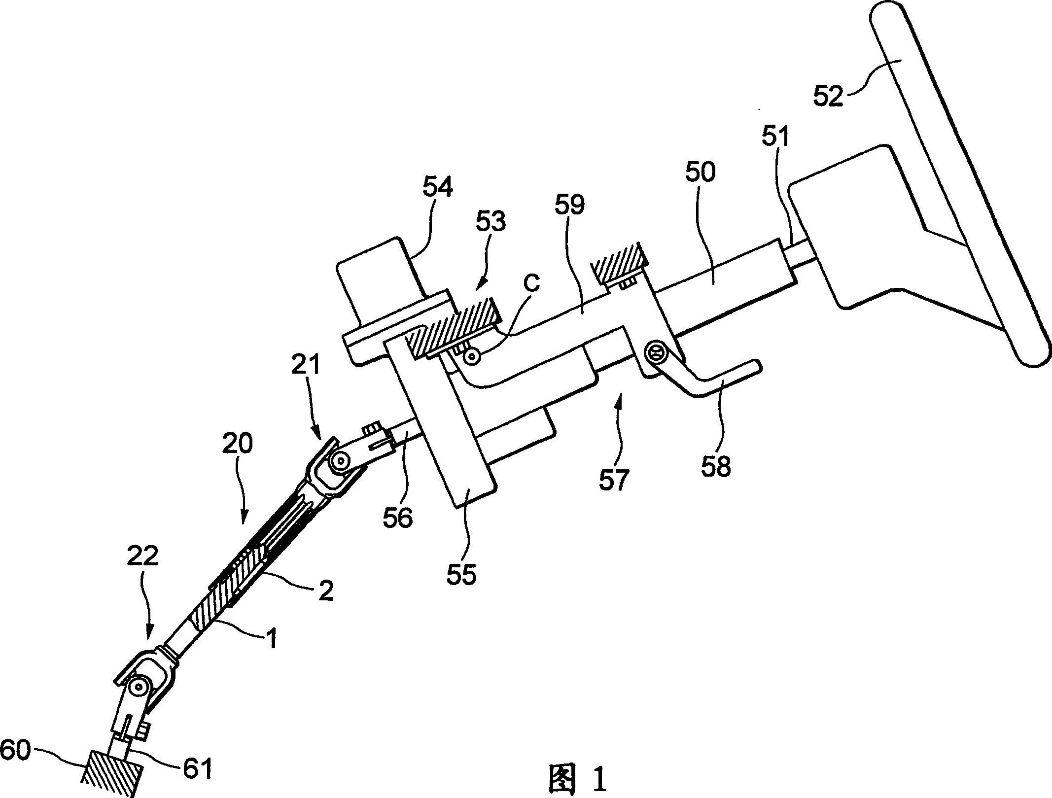
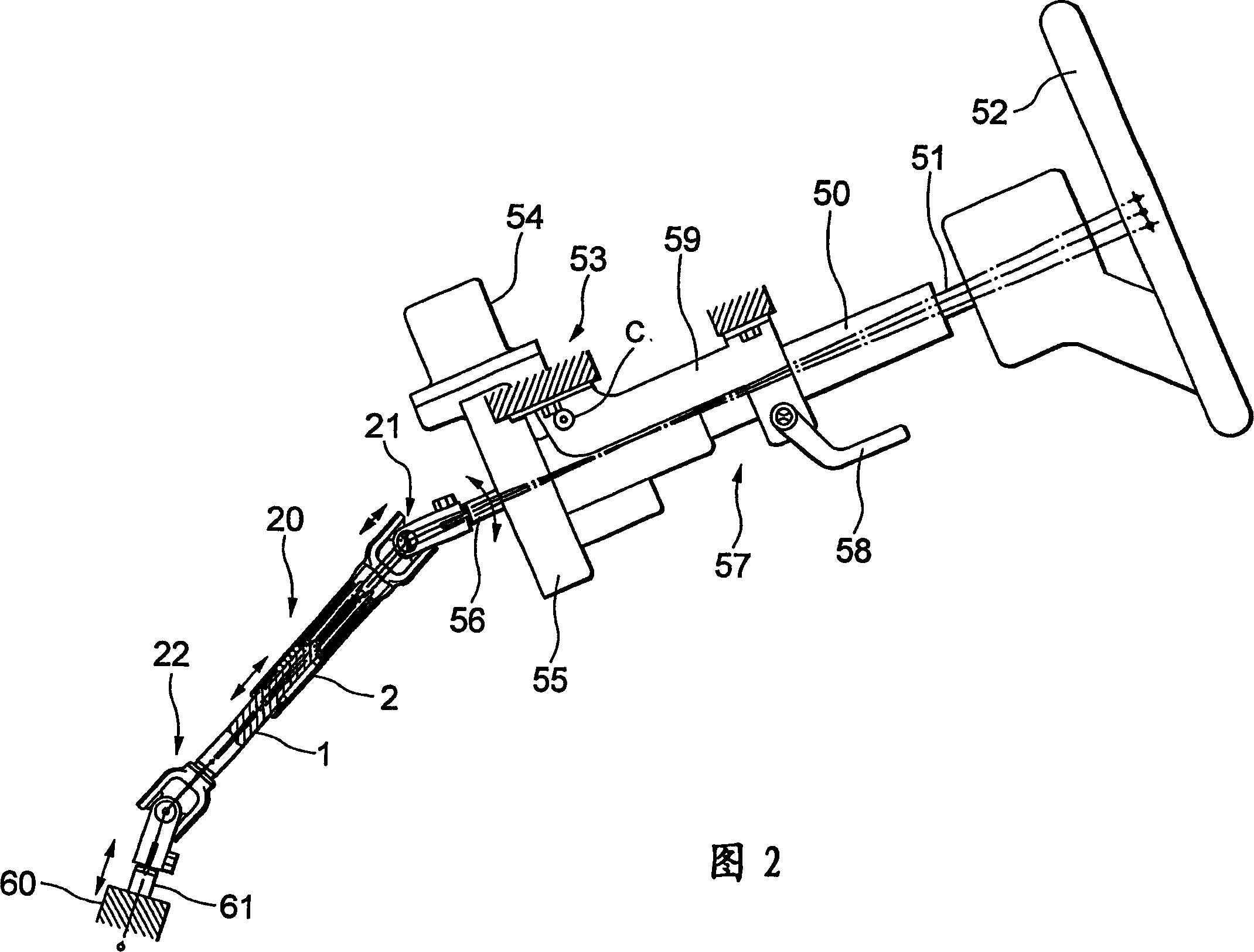
[0066] 1 is a schematic diagram of a steering device for a vehicle according to a first embodiment of the present invention, and FIG. 2 is a schematic diagram of the steering device for a vehicle shown in FIG. 1, showing the highest and lowest degrees of inclination, and for explaining various axes. to the displacement.

[0067] The steering shaft 51 is rotatably supported on the steering column 50 , and a steering wheel 52 is provided on the upper portion of the steering shaft 51 .

[0068] The steering column 50 is provided with a column-assisted electric steering device 53, and the column-assisted electric steering device 53 is provided with a motor 54 for assisting power, a gear set 55 used as a reducer, and a gear set 55 used for high-speed rotation. An output shaft 56 that outputs the steering force assisted by the electric motor 54 and the like.

[0069] A tilt mechanism 57 is also provided on the steering column 50 . When the operation lever 58 is operated, the steer...

no. 2 example

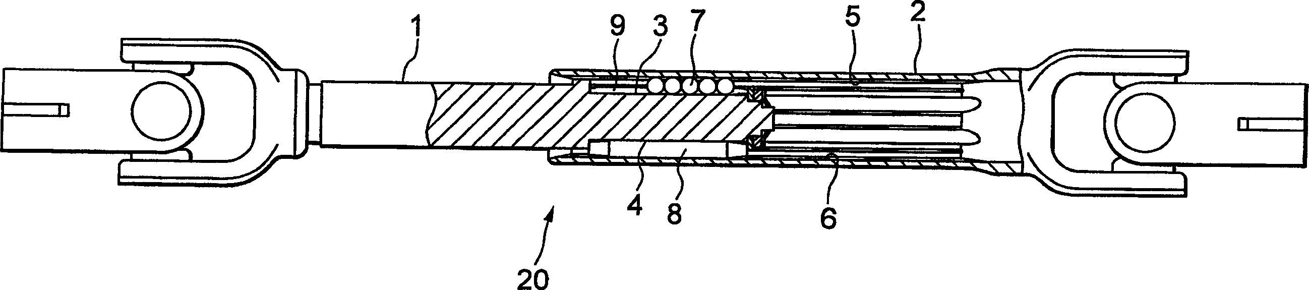
[0125] 6 is a schematic diagram of a steering device for a vehicle according to a second embodiment of the present invention. Fig. 7 is a schematic diagram of the steering device for a vehicle shown in Fig. 6, showing its telescoping and sliding state. FIG. 8 is a view showing only the center line of FIG. 7 in a state where the intermediate shaft is extended or shortened by telescopic sliding.

[0126] The second embodiment has a columnar structure that has a telescoping function in addition to the tilting function, so that the entire steering column 50 can move in the axial direction. In this case, the intermediate shaft 20 needs to be able to expand and contract freely.

[0127] As shown in Figure 6, a long hole 31 for telescopic operation is formed on the bracket 59 fixed on the vehicle body side, and another long hole for telescopic operation is formed on the support bracket 32 ​​arranged on the steering column 50. 33.

[0128] As shown in FIG. 7 , the position of the u...


PUM


Abstract

There is disclosed a steering apparatus for a vehicle in which a steering power of a steering shaft is assisted by a column-assist type electric power steering apparatus so that the steering power is transmitted to steer the wheels by means of a steering mechanism, in which a telescopic shaft with a male shaft and a female shaft fitted to each other to be mutually unrotatable and slidable is interposed between an output shaft of said column-assist type electric power steering apparatus and an input shaft of the steering mechanism.

Description

technical field [0001] The present invention relates to a steering device for a vehicle, wherein the steering force of the steering shaft is assisted by a column assist type electric steering device so that the steering force with increased torque is transmitted through a telescopic intermediate shaft so that when turning The wheels are steered by the steering mechanism. Background technique [0002] In Japanese Patent Application Laid-Open No. 1-145670, an intermediate shaft is interposed between the output shaft of the column-assisted electric steering device and the pinion shaft of the steering gear. A shock absorber for reducing the reaction force from the road surface is provided on the intermediate shaft. However, the intermediate shaft is not lengthened and / or shortened axially. [0003] Figure 9 to Figure 12 A steering device for a vehicle according to the prior art is shown. According to the prior art, an intermediate shaft that is collapsible in a secondary col...

Claims


Application Information

Patent Timeline
Patent Type & Authority Applications(China)
IPC IPC(8): B62D1/20B62D1/185B62D5/04F16C3/03F16C3/035F16D3/06
CPCB62D1/185F16C3/035B62D1/20F16D3/065F16C2326/24F16C29/123F16D2300/22Y10T74/20834
Inventor 山田康久
Owner NSK LTD
Why Eureka
Try Eureka