
Light-emitting diode and its manufacturing method

A technology of light emitting diode and manufacturing method, applied in the field of lighting, can solve the problems of poor electrical and thermal conductivity of sapphire substrate, current concentration effect, small contact area and the like

Inactive Publication Date: 2006-03-08
东莞市福地电子材料有限公司
View PDF0 Cites 2 Cited by
  • Summary
  • Abstract
  • Description
  • Claims
  • Application Information

AI Technical Summary

Problems solved by technology

[0003] The purpose of the present invention is to overcome the shortcomings of the above-mentioned prior art, to provide a light-emitting diode that can effectively solve the problems of poor electrical and thermal conductivity of the sapphire substrate and the problem of easy current concentration effect, and has good reliability and long life.
In this way, on the one hand, the sapphire substrate with poor heat dissipation can be replaced by a substrate with better heat dissipation; The problem of small area contact area can avoid the problem of current concentration effect; so it can effectively protect the luminous body and prolong its working life

Method used


Image

  • Light-emitting diode and its manufacturing method
  • Light-emitting diode and its manufacturing method
  • Light-emitting diode and its manufacturing method

Examples


Embodiment Construction

[0021] The present invention will be further described below in conjunction with accompanying drawing.

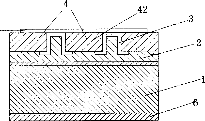
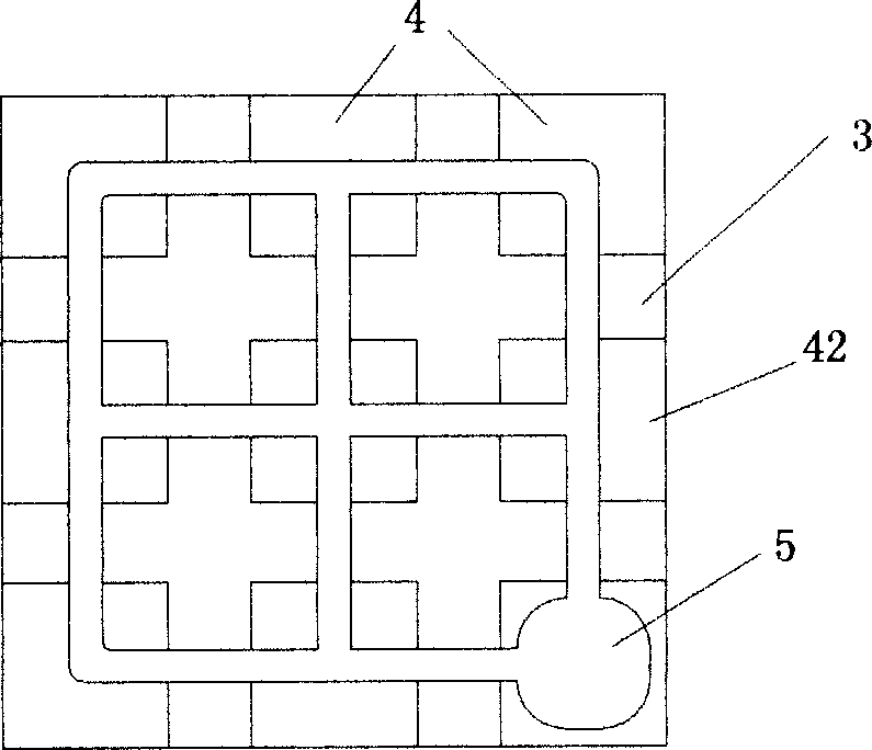
[0022] attached figure 1 with 2 In the light-emitting diode of the illustrated embodiment, the substrate 1 is a P-type contact electrode 2 composed of three metal layers of gold, nickel, and gold, and the P-type contact electrode 2 has light-emitting single packets 42 arranged in a matrix. A reflective insulating film 3 formed by interlaced lamination of silicon dioxide layers and silicon nitride layers is provided between the single packages 42 (the reflective insulating film 3 not only has the function of isolating adjacent light-emitting single packages 42, but also has the function of reflecting light out to improve the light output rate), the reflective insulating film 3 stretches between the P-type contact electrode 2 and the light-emitting single package 42, and forms a surrounding around the contact surface of the light-emitting single package 42 and the P-type con...


PUM


Abstract

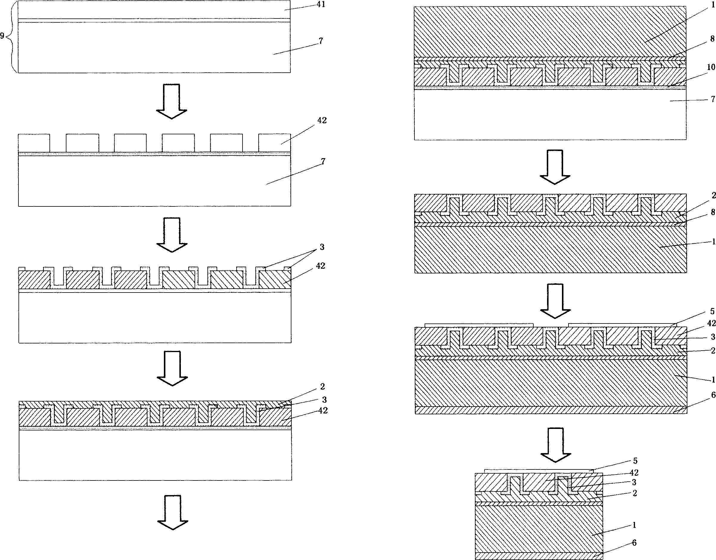
The LED includes following structure: P type contact electrode on a base plate 1; luminous single package on the upper array of the p type electrode; reflection insulation film composed of cross laminated silicon dioxide layer and silicon nitride layer is located between luminous single packages; N type contact electrode in cancellate shape is on luminous single packages. Characters of the method are: a thick layer of gold is vaporized on P type electrode and base plate 1; pressing and heating up the two thick gold layers, the method bonds epitaxial wafer with the base plate 1; using quasi molecule laser in short wave, the method exposes sapphire base plate 7, acts on buffer layer, and puts it in tube inside high-temperature furnace with hedrogen cloride being inducted to in order to peel off plate 7. The LED solves issues: poor electrical and heat conductivities of plate 7; and effect of current concentration. The LED possesses advantages of good reliability and long service life.

Description

technical field [0001] The invention relates to a light-emitting diode technology, in particular to a structure of a light-emitting diode used in the lighting field and a manufacturing method thereof. Background technique [0002] Compared with ordinary lighting fixtures, light-emitting diodes have the advantages of high reliability, high efficiency, long life, full solidification, and low power consumption. They have great potential in the fields of large-screen display, traffic light information indication, and general light display and indication. It is expected to replace the current incandescent and fluorescent lamps in the future and become a green lighting source in the 21st century. But now generally light-emitting diodes use sapphire as the substrate and place them on the light-emitting surface; in addition, due to structural limitations, the N-type contact electrodes must be placed on one side or around the light-emitting body. The disadvantages of this structure ...

Claims


Application Information

Patent Timeline
Patent Type & Authority Applications(China)
IPC IPC(8): H01L33/00H01L33/36
Inventor 彭少鹏
Owner 东莞市福地电子材料有限公司
Learn More