Concrete-bar straightening cutting machine

A cutting machine and steel bar technology, applied in the field of steel bar straightening and cutting machine, can solve the problems of steel bar raw material waste, high labor intensity of workers, low production efficiency, etc., achieve high automation control, reduce labor intensity, and improve production efficiency.

Inactive Publication Date: 2006-03-08
冯广建
View PDF0 Cites 12 Cited by
  • Summary
  • Abstract
  • Description
  • Claims
  • Application Information

AI Technical Summary

Problems solved by technology

[0002] At present, in the construction of engineering buildings, it is usually necessary to use steel bars as the skeleton of cement components, so the disc-shaped steel bars must be straightened. The existing method of straightening steel bars is to first pull the disc-shaped steel bars to the Cut after a certain distance; then one end of the steel bar is spliced ​​to the fixing device, and the other end is spliced ​​to the fixing ring of the stretching device. After the steel bar is straightened, the steel bar is cut into sections with a shear or cutter. The workers of this processing method have high labor intensity and low production efficiency, and because the twisted joints at both ends of the steel bar need to be cut before use, resulting in waste of steel bar raw materials, it is difficult to meet the current people's requirements for high production efficiency and material conservation

Method used


Image

  • Concrete-bar straightening cutting machine
  • Concrete-bar straightening cutting machine
  • Concrete-bar straightening cutting machine

Examples


Embodiment Construction

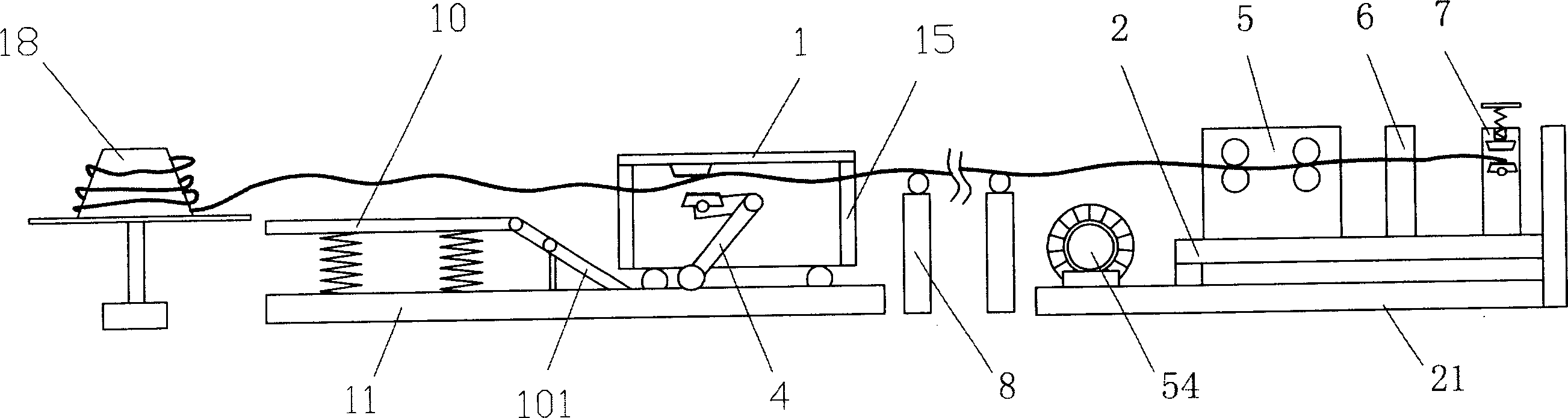
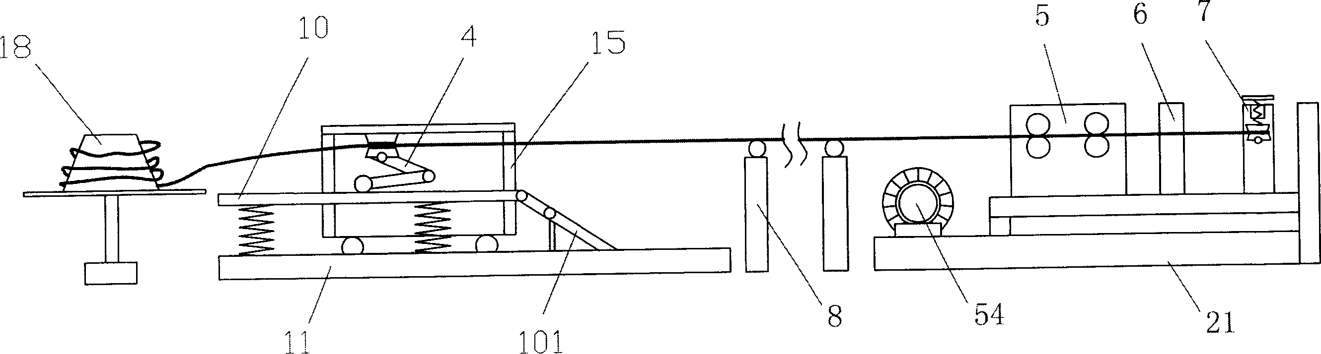
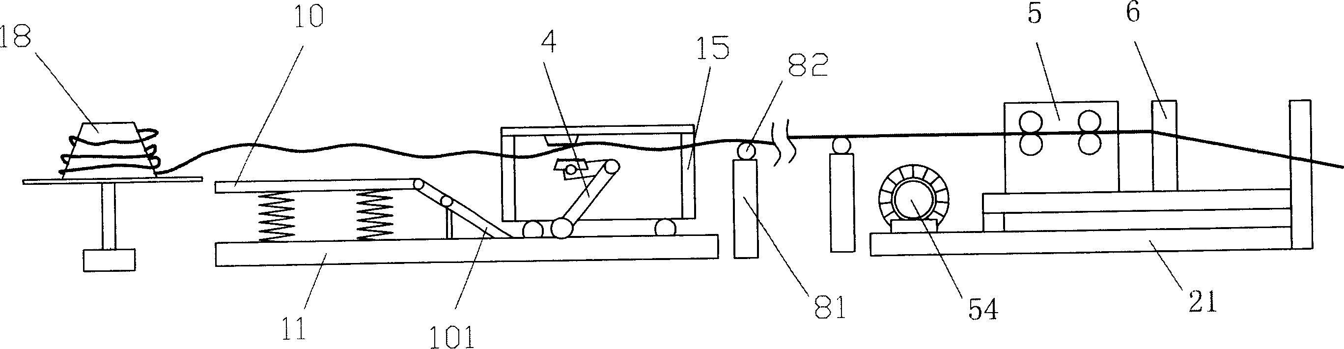
[0024] refer to Figure 5 , Figure 6 , Figure 7 , Figure 8 , Figure 9 , Figure 10 , a steel bar straightening and cutting machine, including a feeding device 18 for placing a disc-shaped steel bar, a reciprocating automatic clamping and straightening mechanism 1, a feeding, cutting, and locking device 2, and a feeding device 18 used in this product It is a turntable, and the reciprocating automatic clamping and straightening mechanism 1 includes a base 11 fixed on the ground. The base 11 is provided with a guide device 10 with an inclined guide bridge 101. The base 11 is provided with a guide groove, and the guide A mobile frame 15 driven by a power unit 14 is provided on the groove, and an upper tooth plate 12 and a rocker arm assembly 4 that can move along the guide device 10 are installed above the frame 15. The rocker arm assembly 4 Including the curved rod 41 whose middle part is hinged on the vehicle frame 15, the two ends of the curved rod 41 are respectively ...


PUM


Abstract

The invention discloses a steel-bar drawing-in and cutting machine. This device comprises a device for holding the disc-form steel bar, to-and-fro automatic clamping and stretching mechanism, feeding, cutting and locking devices. The to-and-fro mechanism comprises a base which is fixed on the ground and is fitted with a guiding device having and is also fitted with guide slot which has a moving frame driven by power device. The frame comprises an upper toothed plate fitted on upper part of the frame and a rocker which has a crank lever whose middle part in hinged oh the frame and at the two ends of the crank lever are respective movably fitted with a lower toothed plate matched with the upper toothed plate and a guide wheel moving along the guide device. Advantages: it needs no sectional cutting so as to fully utilize raw material and it has better drawing-in effect.

Description

technical field [0001] The invention relates to a steel bar straightening and cutting machine. Background technique [0002] At present, in the construction of engineering buildings, it is usually necessary to use steel bars as the skeleton of cement components, so the disc-shaped steel bars must be straightened. The existing method of straightening steel bars is to first pull the disc-shaped steel bars to the Cut after a certain distance; then one end of the steel bar is spliced ​​to the fixing device, and the other end is spliced ​​to the fixing ring of the stretching device. After the steel bar is straightened, the steel bar is cut into sections with a shear or cutter. The workers of this processing method have high labor intensity and low production efficiency, and because the twisted joints at both ends of the steel bar need to be cut before use, the waste of steel bar raw materials is caused, which is difficult to meet the requirements of people's production efficiency...

Claims


Application Information

Patent Timeline
Patent Type & Authority Applications(China)
IPC IPC(8): B21F1/02B21F11/00
Inventor 冯广建
Owner 冯广建
Why Eureka
Try Eureka