Ultrasonic probe and ultrasonic diagnosing device
A diagnostic equipment and ultrasonic technology, applied in the field of ultrasonic probes, can solve problems such as non-uniform sound pressure distribution and reduced resolution of ultrasonic probes, and achieve the effect of uniform low-frequency response characteristics and high resolution
- Summary
- Abstract
- Description
- Claims
- Application Information
AI Technical Summary
Problems solved by technology
Method used
Image
Examples
no. 1 example
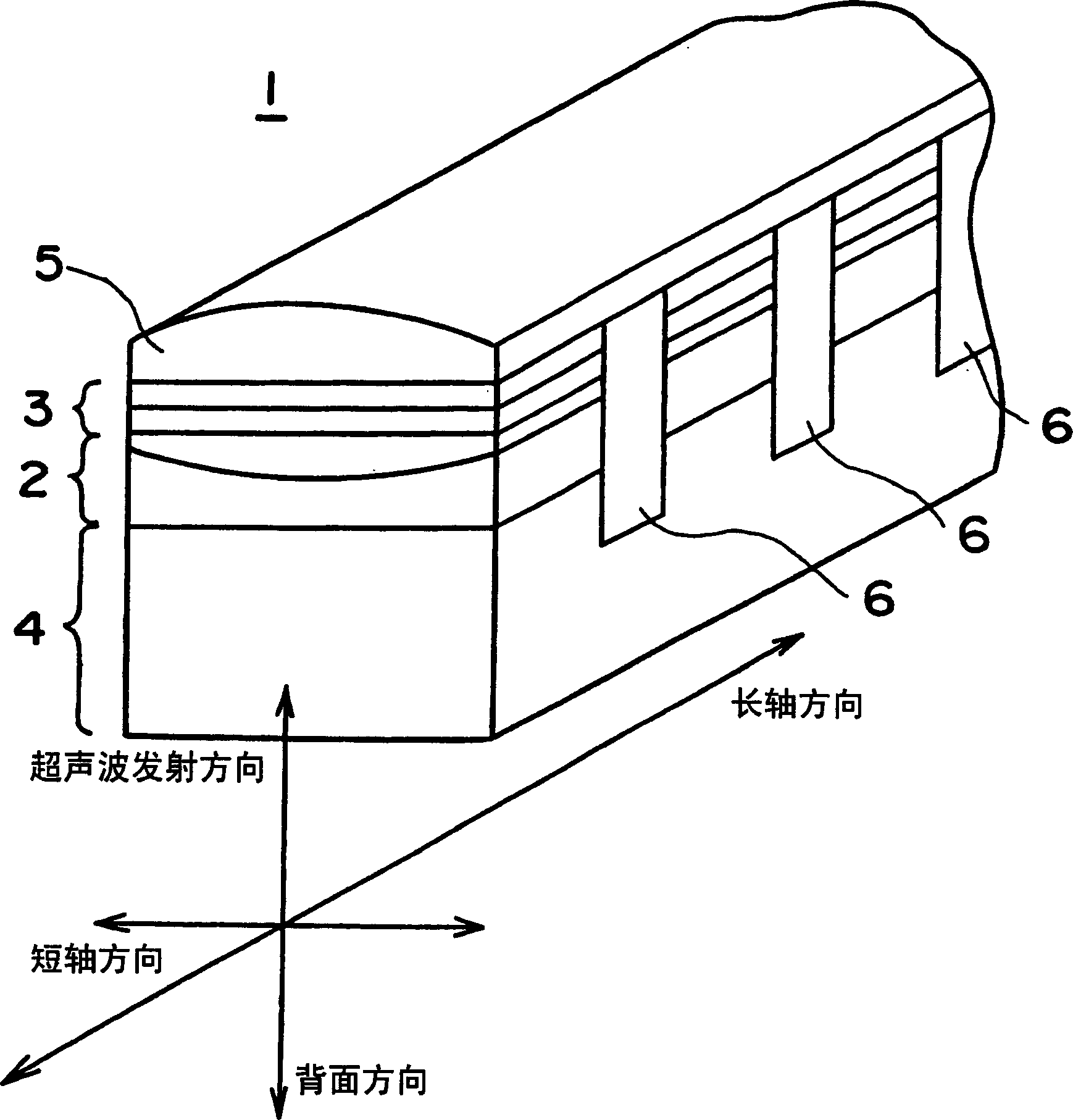
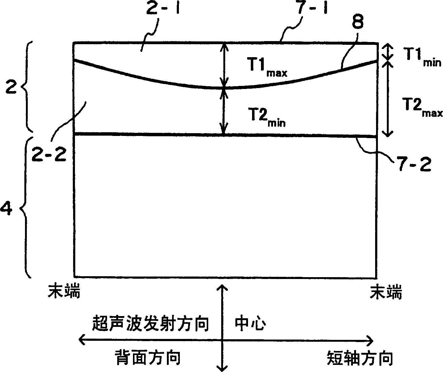
[0041] will refer to Figure 1 to Figure 3 An embodiment of the present invention will be described. figure 1 is a perspective view of the main part of the ultrasonic probe according to the embodiment of the present invention. figure 2 The overall configuration of the ultrasonic diagnostic apparatus according to the embodiment of the present invention is shown. image 3 is a cross-sectional view of a portion related to the piezoelectric layer according to the embodiment.
[0042] exist figure 2 Among them, the ultrasonic pulse sent from the ultrasonic pulse generating circuit 31 is sent to the transmitting unit 32, and is subjected to transmission processing including transmission focusing processing, amplification processing, etc. in the transmitting unit 32. Then, the ultrasonic pulses are sent to the ultrasonic probe 1 through the transmission / reception separation unit 33 . The reflected echo signal received by the ultrasonic probe 1 is sent to the receiving processin...
no. 2 example
[0052] Figure 7 A sectional view of a piezoelectric layer portion of an ultrasonic probe according to a second embodiment of the present invention is shown. The difference between the second embodiment and the first embodiment lies in the two-layer structure of the piezoelectric layer 2 and the adjustment layer 9 provided on the back side of the piezoelectric layer 2 . First, the piezoelectric layer 2 includes two mutually laminated planar piezoelectric layers 2-3 and 2-4, which are also formed. The adjustment layer 9 formed on the back side of the piezoelectric layer 2-4 includes a material having an acoustic impedance approximately equal to that of the piezoelectric layer 2, such as a metal including ceramics, aluminum, copper, or the like. Further, the backing layer 4 includes a material whose acoustic impedance is much smaller than that of the adjustment layer 9 and whose attenuation rate is greater than the attenuation rate of the adjustment layer 9 . For example, the ...
no. 3 example
[0055] Figure 8 A partial sectional view of the piezoelectric layer of an ultrasonic probe according to a third embodiment of the present invention is shown. The difference between the third embodiment and the first embodiment is that the adjustment layer 9 is provided on the back side of the piezoelectric layer 2 . In other words, the characteristic parts of the first embodiment and the second embodiment are combined with each other, so that both the effect of the first embodiment and the effect of the second embodiment can be obtained. That is, uniform low-frequency sound pressure in the minor axis direction, and an aperture variable function for obtaining a narrower beam at each frequency than in the past can be realized.
PUM
 Abstract
Description
Claims
Application Information
 - R&D
- Intellectual Property
- Life Sciences
- Materials
- Tech Scout
- Unparalleled Data Quality
- Higher Quality Content
- 60% Fewer Hallucinations
Browse by: Latest US Patents, China's latest patents, Technical Efficacy Thesaurus, Application Domain, Technology Topic, Popular Technical Reports.
© 2025 PatSnap. All rights reserved.Legal|Privacy policy|Modern Slavery Act Transparency Statement|Sitemap|About US| Contact US: help@patsnap.com


