Engineered meridian tyre blank molding method

A molding method and radial tire technology are applied in the field of tire manufacturing, which can solve the problems of low molding efficiency and hidden quality problems of tires, and achieve the effects of improving efficiency and increasing strength.

Active Publication Date: 2006-02-22
TRIANGLE TIRE
View PDF0 Cites 11 Cited by
  • Summary
  • Abstract
  • Description
  • Claims
  • Application Information

AI Technical Summary

Problems solved by technology

[0007] In order to overcome the technical deficiencies of the existing engineering radial tire embryo forming process, the invention provides a segmented forming method of the engineered radial tire embryo. The purpose of the forming method is to provide a new engineering radial tire forming process to solve the problem of forming efficiency. Low, causing potential hidden dangers to the internal quality of the tire and can produce larger-sized engineering radial tires as much as possible without adding new carcass steel wire specifications

Method used


Image

  • Engineered meridian tyre blank molding method
  • Engineered meridian tyre blank molding method
  • Engineered meridian tyre blank molding method

Examples


Embodiment 1

[0021] The segmented molding process of the engineering radial tire embryo of the present invention is to boldly and reasonably split the molding process of the engineering radial tire embryo, so that the molding of the engineering radial tire embryo is completed in three stages, that is, three-stage molding. The specific equipment used in the forming process, such as: simulation winding machine, flat drum, half-drum forming drum, gripper, clamp ring, spreader, reverse-wrapping capsule, belt layer bonding drum, and the structure of the shaping drum The structure is well known to those skilled in the art. The specific methods used in the three-stage molding process, such as: simulated winding, airtight rubber, carcass bonding, carcass finger wrapping, buckle ring, rubber core pressing, The operations of shoulder pad winding and carcass turnup are also well known to those skilled in the art. The present invention adopts three-stage, seven-drum forming, and is equipped with four ...

Embodiment 2

[0033] In this embodiment, the second section is composed of a subsection. In this subsection, only one semi-drum-type building drum with adjustable width is used to complete the molding operation of the second section of composite parts. In addition, other operating steps are the same as in Example 1. It is exactly the same, and the description will not be repeated here.

Embodiment 3

[0035] In this embodiment, the lamination method is used instead of the simulated winding, and the specific forming process is as follows:

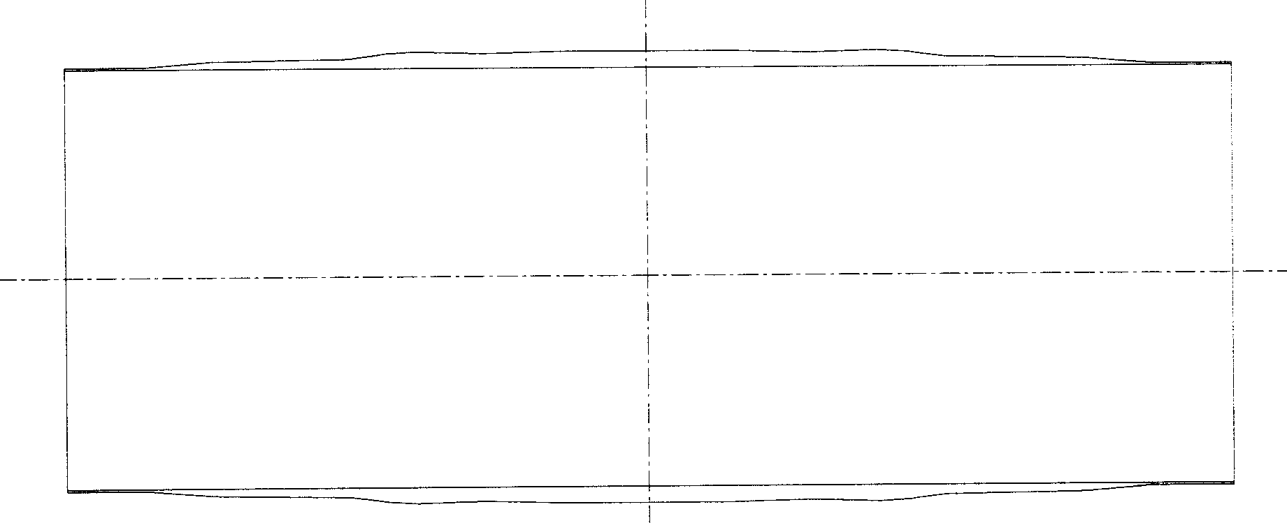
[0036] One section: use a flat drum with continuously adjusted diameter to carry out airtight glue, carcass lamination and adhesive glue lamination, and finally form a section of carcass tube composite (such as figure 1 shown), the working process is:

[0037] First, the diameter of the flat drum is adjusted to the working diameter, and the airtight glue is applied. After the bonding, the joint parts are processed and compacted. The carcass joints are sewed together, and then the carcass is bonded again with adhesive glue. Finally, a section of composite parts is rolled and marked with a pressure roller, and finally a section of carcass tube composite parts is bonded. A length of carcass tube composite is unloaded from the flat drum.

[0038] Second stage: Due to the faster speed of the carcass tube composite produced in the first stage...


PUM


Abstract

The invention relates to a method for forming a green tyre of an engineering radial-type tyre, which contains: the first: using a flat drum to deposit the vacuum cement and carcass and artificially wind the adhesive gum, to form one-stage carcass bobbin composite element. The second: sending the one-stage carcass bobbin composite element to the spreader to enlarge, and sending to the forming drum, pressing with a compression roller; the shoulder pad gum winding artificially and packing oppositely; and winding the tyre-side with a artificial coiler to complete the forming of second-stage composite element. The third: containing a bet side and a shaping side, depositing by a B&T drum to complete the belt deposition and depositing with tread base gum or transition film to form a belt complex; setting the second-stage composite element to a shaping drum, transporting the belt complex to the center of the shaping drum and assembling with the second-stage composite element, rolling the belt complex with a compression roller; tyre surface winding with a artificial coiler to complete the green tyre forming process.

Description

technical field [0001] The invention belongs to the technical field of tire manufacture, in particular to a segmented molding process method of an engineering radial tire embryo. Background technique [0002] As we all know, the tires used for engineering vehicles are referred to as engineering tires. This type of tire is characterized by large tire dimensions, large load capacity, and difficult molding process. Domestic and foreign manufacturers are mainly engaged in engineering tires with oblique structures. In recent years, they have developed and produced All-steel engineering radial tires are produced, and its molding process is a continuation of the truck radial tire process, basically adopting a one-time molding process: [0003] That is, the belt layer (two layers, three layers or more layers) is pasted on the auxiliary drum and combined with the tread to form a belt layer composite. [0004] On the main drum, the sidewall, spigot, molding rubber, inner liner, carca...

Claims


Application Information

Patent Timeline
IPC IPC(8): B29D30/20
Inventor 丁玉华单国玲王波刘丽郑乾
Owner TRIANGLE TIRE
Why Eureka
Try Eureka