
Perpendicular magnetic recording medium, method for preparing the same and magnetic recording equipment

A magnetic recording medium and magnetic recording technology, applied in magnetic recording, magnetic recording layer, data recording, etc., can solve problems such as difficult to increase recording density, difficult to improve medium performance, etc., and achieve the effect of improving recording capacity

Active Publication Date: 2006-02-15
FUJI ELECTRIC CO LTD
View PDF4 Cites 1 Cited by
  • Summary
  • Abstract
  • Description
  • Claims
  • Application Information

AI Technical Summary

Problems solved by technology

Due to the above reasons, it is difficult to improve the medium performance and increase the recording density of the bottom layer containing spherical or ellipsoidal grains

Method used


Image

  • Perpendicular magnetic recording medium, method for preparing the same and magnetic recording equipment
  • Perpendicular magnetic recording medium, method for preparing the same and magnetic recording equipment
  • Perpendicular magnetic recording medium, method for preparing the same and magnetic recording equipment

Examples


Embodiment 1

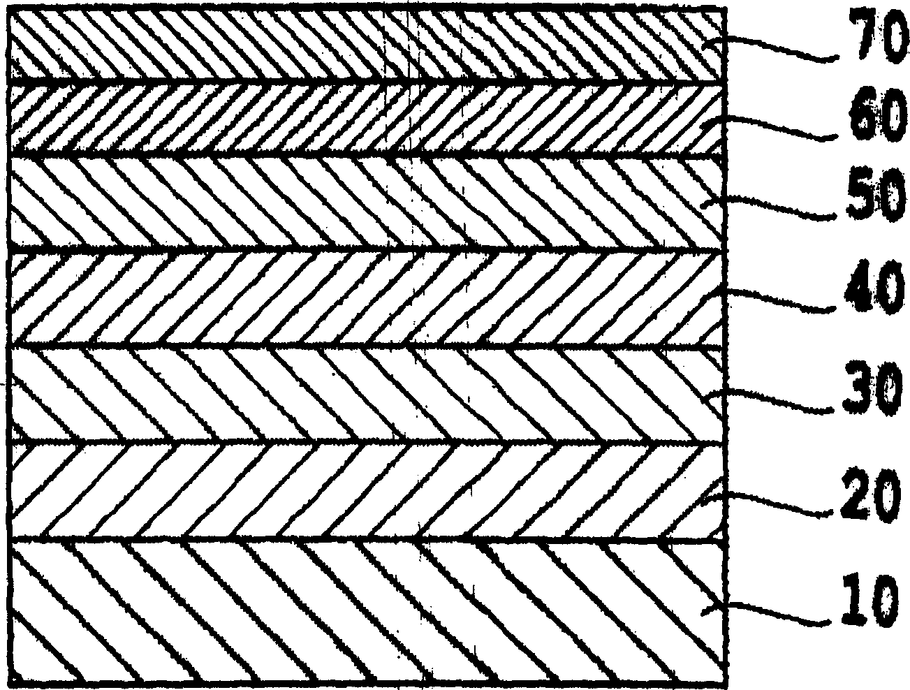
[0077] This example produced a figure 1 Two-layer vertical media of the structure shown. The non-magnetic substrate 10 used is a chemically strengthened glass substrate (for example, N-5 glass substrate produced by HOYA Corporation) having a smooth surface. After cleaning, the substrate was placed in a DC magnetron sputtering device, and was coated with Co in a 5mTorr (0.67Pa) argon 91 Zr 5 Nb 4 The target forms a soft magnetic backing layer 20 composed of amorphous CoZrNb with a thickness of 150 nm. Then use Ni in 30mTorr (4.0Pa) argon atmosphere 84 Fe 13 Si 3 The target forms a seed layer 30 having a thickness of 10 nm and consisting of soft magnetic NiFeSi.

[0078] Next, use Ru under the pressure of 30mTorr (4.0Pa) 95 Si 5 The target deposits a RuSi underlayer 40 with a thickness of 10 nm. The gas in the DC magnetron sputtering equipment is all argon at the beginning of the deposition. After starting the deposition, start adding nitrogen to the argon to maintain...

Embodiment 2

[0082] A two-layer vertical medium was obtained by the same procedure as in Example 1, except that the bottom layer 40 was formed as follows. In 30mTorr (4.0Pa) Argon atmosphere 95 Si 5 A RuSi underlayer 40 is deposited with a thickness of 5 nm. After deposition starts, press the Figure 5 Varying the sputtering input power is shown. The gas in the equipment was argon throughout the deposition steps.

Embodiment 3

[0084] A two-layer vertical medium was obtained by the same procedure as in Example 1, except that the bottom layer 40 was formed as follows. In 30mTorr (4.0Pa) Argon atmosphere 95 Si 5 A RuSi underlayer 40 is deposited with a thickness of 5 nm. After deposition starts, press the Image 6 Varying the sputtering input power is shown. The gas in the equipment was argon throughout the deposition steps.


PUM

PropertyMeasurementUnit
particle diameteraaaaaaaaaa
coating thicknessaaaaaaaaaa

Abstract

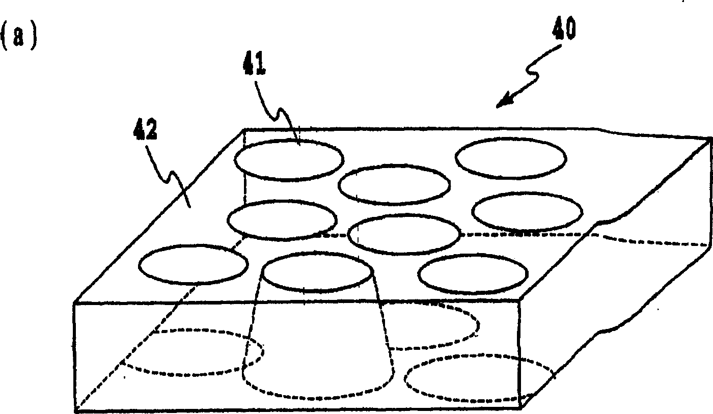
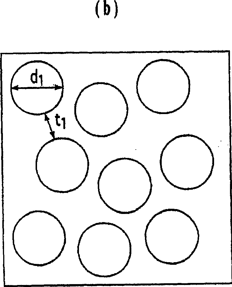
The object of the present invention is to provide a perpendicular medium, which can suppress the dispersion of alignment and reduce the size of magnetic clusters in the magnetic recording layer by forming the isolation structure of the bottom layer by a simple method like the conventional process for producing continuous film medium. Perpendicular media also have a higher recording density due to the thinner underlying film. A perpendicular magnetic recording medium comprises at least one underlayer and a magnetic recording layer sequentially laminated on a non-magnetic substrate. The bottom layer is composed of crystal grains and amorphous grain boundaries, and the shape of the grains satisfies the following relationship: (area of ​​the bottom region at the initial stage of growth) > (area of ​​the top region).

Description

[0001] related application [0002] This application is based on and claims priority from Japanese Application No. 2004-201115 filed on July 7, 2004, the contents of which are incorporated herein by reference. technical field [0003] The present invention relates to a perpendicular magnetic recording medium mounted on various magnetic recording devices, a manufacturing method thereof, and a magnetic recording device using the perpendicular magnetic recording medium. technical background [0004] As a technology capable of obtaining high-density magnetic recording, perpendicular magnetic recording systems are being regarded as possible substitutes for conventional longitudinal magnetic recording systems. In a perpendicular magnetic recording system, the direction of magnetization during recording is perpendicular to the plane of the medium, while in a longitudinal magnetic recording system, the direction of magnetization during recording is along the plane of the medium. Th...

Claims


Application Information

Patent Timeline
Patent Type & Authority Applications(China)
IPC IPC(8): G11B5/66G11B5/73G11B5/84
CPCG11B5/65G11B5/7325G11B5/85G11B5/7377G11B5/737G11B5/658G11B5/657
Inventor 渡边貞幸酒井泰志
Owner FUJI ELECTRIC CO LTD
Learn More