
Stock level detecting method

A technology of material level detection and material level, which is applied in the field of material level detection, can solve the problems of low precision, unstable precision, high price, etc., and achieve the effect of wide application of materials, good economy and high measurement accuracy

Inactive Publication Date: 2006-02-08
ZHEJIANG UNIV
View PDF0 Cites 2 Cited by
  • Summary
  • Abstract
  • Description
  • Claims
  • Application Information

AI Technical Summary

Problems solved by technology

Due to its poor reliability and requiring a lot of maintenance work, the steel belt level gauge has been gradually eliminated
Ordinary capacitive level gauges are less accurate due to the influence of dielectric constant, temperature, humidity, etc. of the medium and environment.
Radar level gauges have high level accuracy, high resolution, and high reliability, but they are expensive and cannot be used in large quantities
Servo level gauges also have high level accuracy, and the high-end ones also have the function of measuring the oil-water interface, but they are also more expensive than radar level gauges and are difficult to use in large quantities
The static pressure measurement method has high measurement accuracy and high reliability, but its applicability is poor, and it is prone to problems such as clogging of the measurement port, so it has certain limitations
The currently used ultrasonic material level gauge is directly installed above the measured medium, using a low-power transceiver integrated ultrasonic sensor, and through the principle of measuring time difference, the level of material level is measured. Due to the nature of the material, the accuracy of this method is low. Moreover, when it is applied in a dusty environment, the sensitivity of the probe will be significantly reduced as the amount of radiated flour dust adhering to the ultrasonic level gauge increases.

Method used


Image

  • Stock level detecting method
  • Stock level detecting method
  • Stock level detecting method

Examples


Embodiment 1

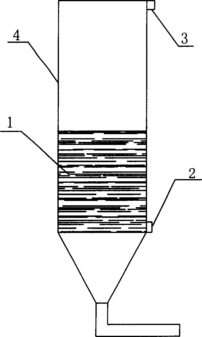
[0021] Such as figure 1 As shown, a vibration signal with a frequency of 30 kHz and a power of 10 watts is applied at the bottom transmitting position 2 on the outer surface of the silo 4 silo wall, and the vibration signal is received at the top receiving position 3 on the outer surface of the silo 4 silo wall. For a plexiglass silo with a diameter of 300mm and a wall thickness of 5mm, polyethylene particles with a built-in particle size of 0.3mm are used as static materials. When the height of the material level increases by 1cm, the amplitude of the vibration signal is attenuated by 5%. By comparing the attenuation of the energy of the received vibration signal and the energy of the applied vibration signal, the height of the material level in the silo can be determined.

Embodiment 2

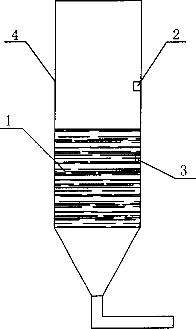
[0023] Such as figure 2 As shown, a vibration signal with a frequency of 20 Hz is applied at the top transmitting position 2 of the inner surface of the silo 4 silo wall, and the vibration signal is received at the bottom receiving position 3 of the inner surface of the silo 4 silo wall. By comparing the difference between the energy of the received vibration signal and the energy of the applied vibration signal, the height of the material level in the silo is determined.

Embodiment 3

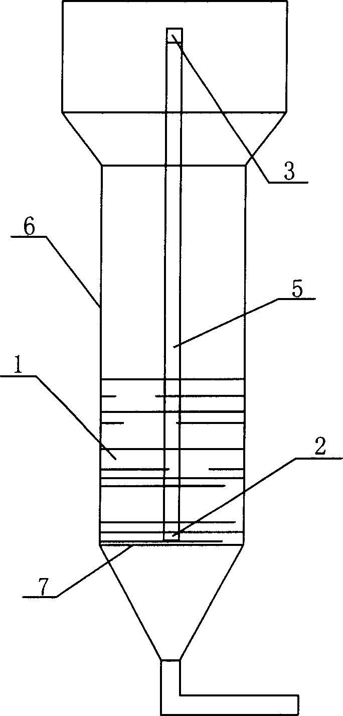
[0025] Such as image 3 As shown, a long sheet 5 is extended from the top of the fluidized bed reactor 6 until it reaches the bottom of the fluidized bed reactor 6, and there is a gas distribution plate 7 at the bottom. The material level in the fluidized bed fluctuates with the blowing of gas. A vibration signal with a frequency of 100 MHz is applied to the transmitting position 2 at the bottom of the elongated sheet 5 and received at the receiving position 3 at the top. By comparing the difference between the energy of the received vibration signal and the energy of the applied vibration signal, the height of the material level in the silo is determined.


PUM

PropertyMeasurementUnit
Diameteraaaaaaaaaa
Particle sizeaaaaaaaaaa

Abstract

The invention discloses a materials bit detecting method which comprises: (1) fixing a vibration signal generator and a vibration signal accepter on the materials bit cask, wherein the vibration signal generator and the vibration signal accepter is fixed on the lower part of the materials bit, while the other one is fixed on the upper part of the materials bit; (2) sending vibration signal by vibration signal generator; (3) accepting the vibration signal by vibration signal accepter; (4) ascertaining the materials bit by the degeneration between the sending position and the accepting position of the vibration signal.

Description

technical field [0001] The invention relates to a detection method, in particular to a material level detection method. Background technique [0002] Existing instruments and methods for measuring material level include: steel belt level gauge, ordinary capacitive level gauge, radar level gauge, servo level gauge, ultrasonic level gauge, static pressure measurement method, etc. Because of its poor reliability and requiring a lot of maintenance work, the steel belt level gauge has been gradually eliminated. Due to the influence of the dielectric constant of the medium and the environment, temperature, humidity, etc., the accuracy of ordinary capacitive level gauges is unstable. Radar level gauges have high level accuracy, high resolution, and high reliability, but they are expensive and cannot be used in large quantities. Servo-type level gauges also have high level accuracy, and the high-end ones also have the function of measuring the oil-water interface, but they are als...

Claims


Application Information

Patent Timeline
IPC IPC(8): G01F23/22G01F23/28
Inventor 阳永荣刘诚午王靖岱
Owner ZHEJIANG UNIV
Learn More