
Cutting method of hole

A technology for machining and machining platforms, applied in the field of hole machining, can solve the problems of difficulty in achieving machining accuracy, increasing size and shape, and small hole deformation, achieving high machining accuracy and reducing size and shape errors. , the effect of preventing deformation and offset

Inactive Publication Date: 2006-01-11
新昌县东升机械制造有限公司
View PDF0 Cites 7 Cited by
  • Summary
  • Abstract
  • Description
  • Claims
  • Application Information

AI Technical Summary

Problems solved by technology

This traditional drilling method is difficult to avoid the deformation and offset of the drill bit during the drilling process, so when the small hole is first drilled, it will cause the small hole to be deformed (such as bending) and increase the size and shape error , beyond the scope of its dimensional tolerance and shape tolerance; and when reaming, the small hole has the effect of guiding the drill bit, so it is difficult to correct by reaming
Especially when drilling multiple holes with strict positional requirements on one workpiece, and drilling holes with the same dimensional tolerance and shape tolerance on multiple workpieces, this traditional drilling method is due to the Requires multiple positioning and clamping of the workpiece, making it more difficult to achieve machining accuracy

Method used


Image

  • Cutting method of hole
  • Cutting method of hole

Examples


Embodiment Construction

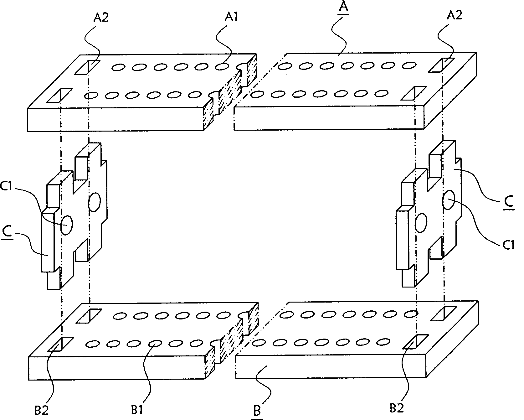
[0012] figure 1 The mold shown includes A template, B template and two supporting positioning splints C, wherein two rows of parallel small orthopedic positioning holes A1 are provided on the A template, and two rows of large orthopedic positioning holes corresponding to the small orthopedic positioning holes are provided on the B template. The orthopedic positioning hole B1, the two ends of the A template and the B template are also provided with supporting holes A2 and B2; two corresponding workpiece positioning parts C1 are respectively provided on the two supporting positioning splints, and the two supporting positioning splints are plugged into the supporting holes In order to ensure the corresponding relationship between the positions of the two templates A and B, make the large and small orthopedic positioning holes on them correspond to each other, and realize the disassembly and connection of the two templates A and B.

[0013] Such as figure 2 As shown, first insta...


PUM


Abstract

A method for machining holes on a workpiece includes such steps as locating a workpiece on a template set consisting of a template with small correcting-locating holes and another template with big ones, clamping the workpiece, fixing the template set onto platform, drilling from the small correcting-locating hole to big one, drilling reversely, broaching from big hole to small hole, and reaming from big hole to small hole.

Description

【Technical field】 [0001] The invention relates to a machining method, in particular to a hole cutting method. 【Background technique】 [0002] At present, when drilling holes on the workpiece, the workpiece is usually placed directly on the (positioning, clamping) processing platform for drilling processing. The specific operation is usually to drill a small hole first, and then ream the small hole to obtain the required size. specification holes. This traditional drilling method is difficult to avoid the deformation and offset of the drill bit during the drilling process, so when the small hole is first drilled, it will cause the small hole to be deformed (such as bending) and increase the size and shape error , beyond the scope of its dimensional tolerance and shape tolerance; and when reaming, the small hole has a guiding effect on the drill bit, so it is difficult to correct it by reaming. Especially when drilling multiple holes with strict positional requirements on on...

Claims


Application Information

Patent Timeline
Patent Type & Authority Applications(China)
IPC IPC(8): B23P13/00
Inventor 张少林
Owner 新昌县东升机械制造有限公司
Learn More