Liquid crystal display device
一种液晶显示装置、液晶元件的技术,应用在非线性光学、仪器、光学等方向,能够解决蓝色纯度低下等问题
- Summary
- Abstract
- Description
- Claims
- Application Information
AI Technical Summary
Problems solved by technology
Method used
Image
Examples
Embodiment 1
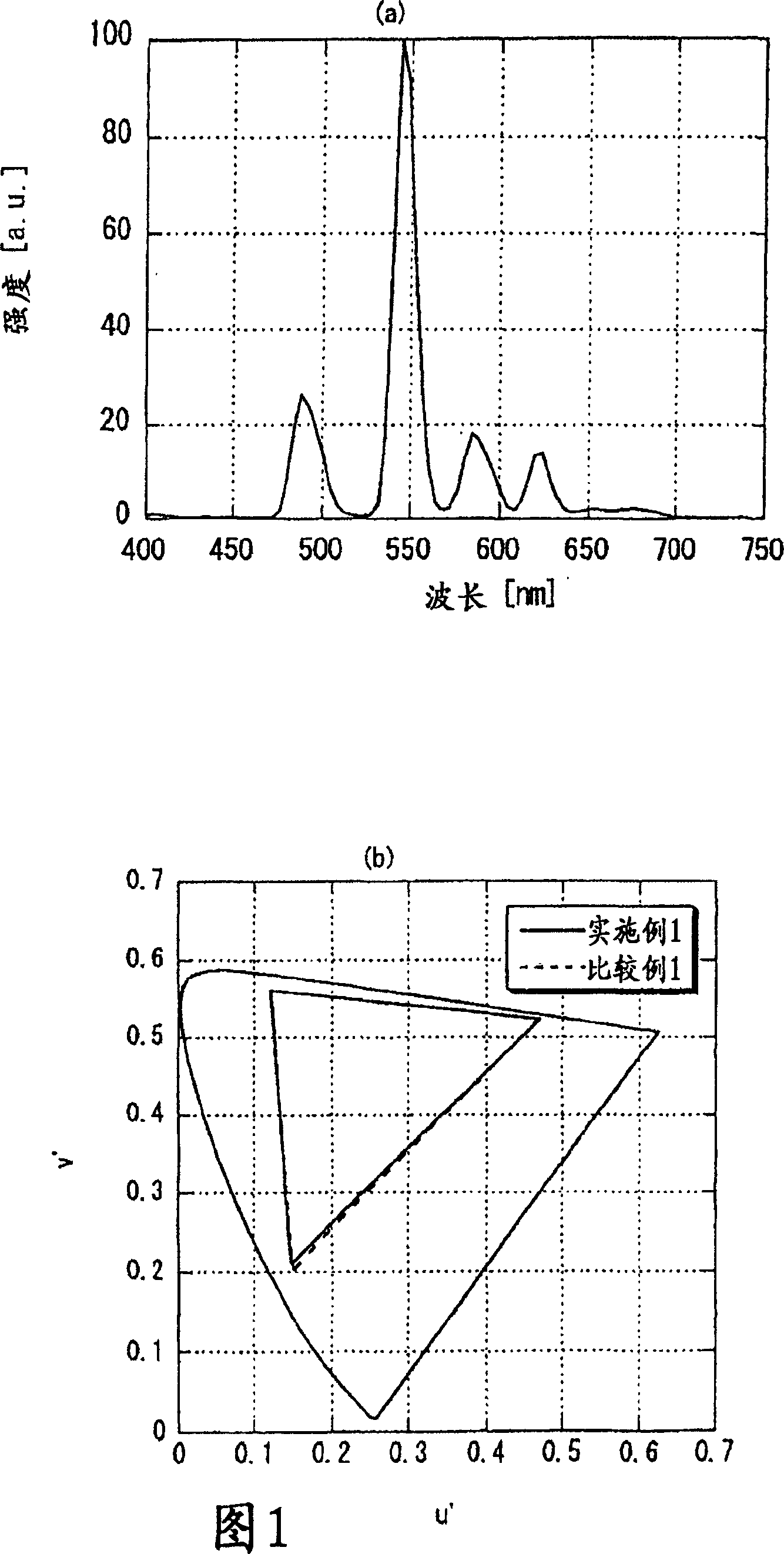
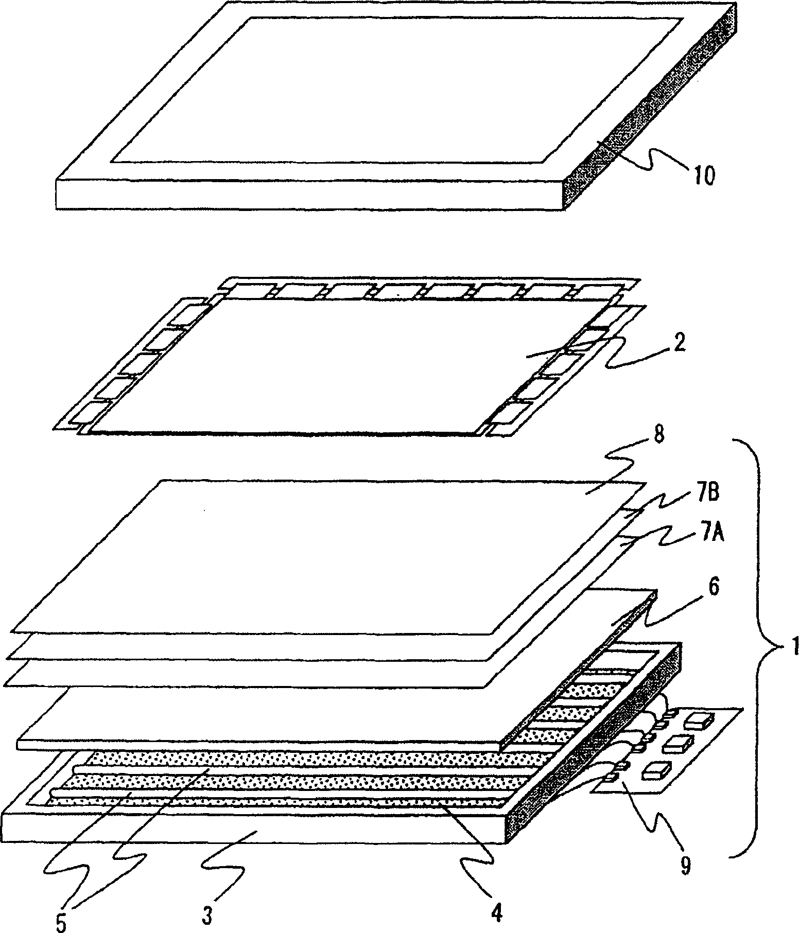
[0086] The liquid crystal display device in this embodiment is the same as the existing structure, and its schematic diagram is as follows figure 2 shown. Different from the existing ones, the green phosphor material used in CCFL is different. In this embodiment, the green phosphor material uses a mixed green phosphor, specifically using LaPO 4 : Tb, Ce and Y 2 SiO 5 : Tb, Ce. Next, the manufacture of CCFLs using these phosphors and the manufacture of liquid crystal display devices using the CCFLs will be described.
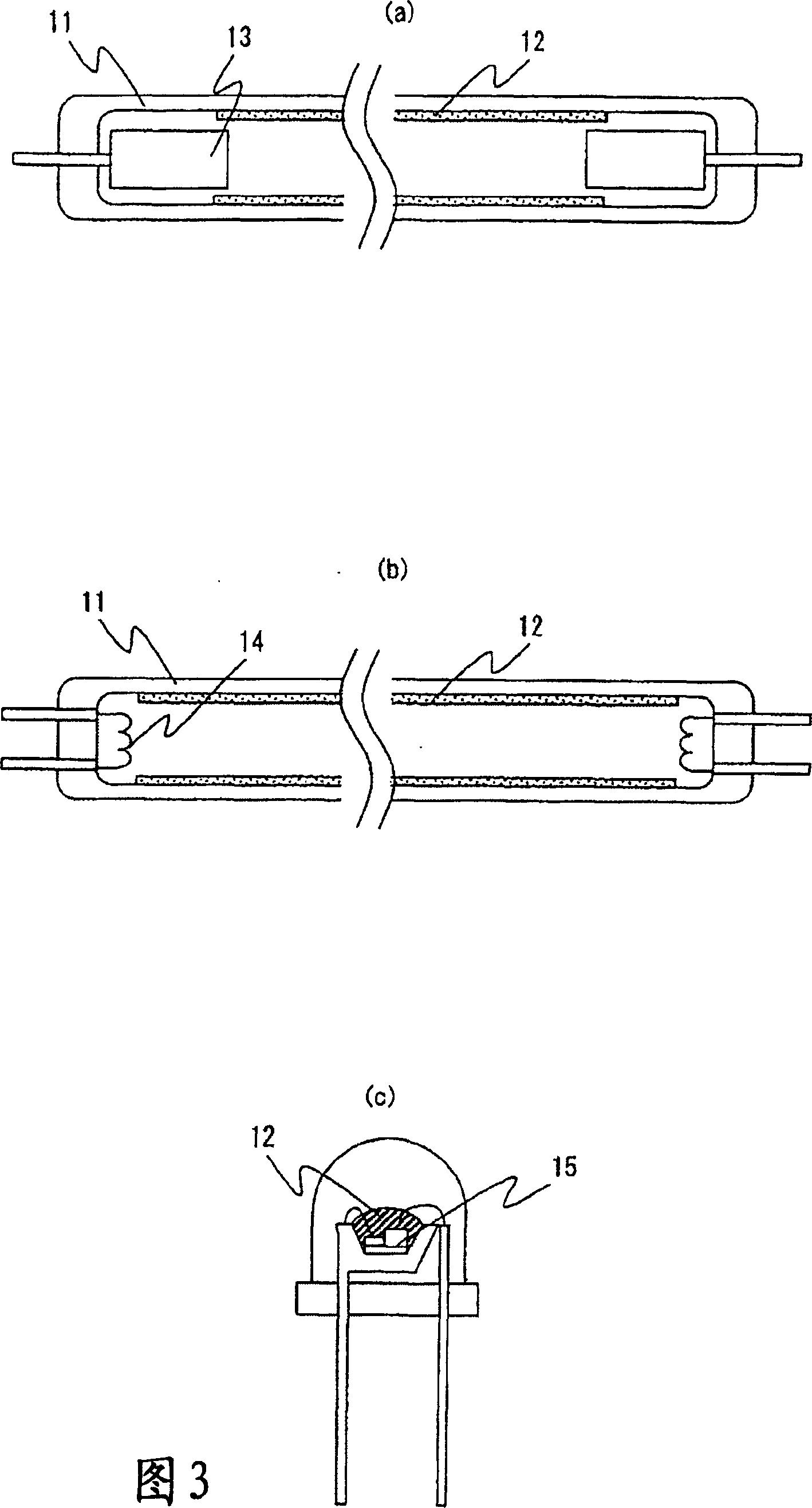
[0087] Schematic diagram of the fabrication steps of CCFL, such as Figure 11 shown. In addition, the structure of the fabricated CCFL is shown in Fig. 3(a). First, a binder such as alumina and various phosphor materials are mixed in an organic solvent called a vehicle. In this example, BaMgAl previously used for blue phosphors and red phosphors were used 10 o 17 :Eu and Y 2 o 3 :Eu. Alternatively, for the green phosphor, use LaPO as previously descr...
Embodiment 2
[0096] Compared with Embodiment 1, this embodiment uses a different mixed green phosphor. Other constitutions are the same as in Embodiment 1. In this embodiment, the mixed green phosphor uses LaPO 4 : Tb, Ce and Y 3 al 5 o 12: Tb, Ce mixed green phosphor. The mixing ratio is set as LaPO in molar ratio 4 : Tb, Ce / Y 3 Al 5 o 12 : Tb, Ce=0.1 / 0.9.
[0097] Figure 12 (a) shows the emission spectra of these mixed green phosphors. The shape of the spectrum and the commonly used LaPO 4 : Tb, Ce are basically the same. In addition, the response characteristic is τ on = 2.8msec, τ off = 4.0msec, with the usual LaPO 4 : Compared with Tb and Ce, it is shortened to about 60%.
[0098] in addition, Figure 12 (b) shows the color reproduction range of the liquid crystal display device obtained in this example. Compared with the characteristics of the liquid crystal display device in Comparative Example 1 described later, the color reproduction range hardly changed. The c...
Embodiment 3
[0101] Compared with Embodiment 1, this embodiment uses a different mixed green phosphor. Other constitutions are the same as in Embodiment 1. In this embodiment, the mixed green phosphor uses LaPO 4 : Tb, Ce and LaOCl: Tb, Ce mixed green phosphor. The mixing ratio is set as LaPO in molar ratio 4 : Tb, Ce / LaOCl: Tb, Ce=0.3 / 0.7.
[0102] Figure 13 (a) represents the emission spectrum of the mixed green phosphor. The shape of the spectrum and the commonly used LaPO 4 : Tb, Ce are basically the same. In addition, the response characteristic is τ on = 2.4msec, τ off = 3.0msec, with the usual LaPO 4 : Compared with Tb and Ce, it is shortened to almost 50%.
[0103] in addition, Figure 13 (b) shows the color reproduction range of the liquid crystal display device obtained in this example. Compared with the characteristics of the liquid crystal display device in Comparative Example 1 described later, the color reproduction range hardly changed. The chromaticity change ...
PUM
| Property | Measurement | Unit |
|---|---|---|
| wavelength | aaaaa | aaaaa |
| wavelength | aaaaa | aaaaa |
| wavelength | aaaaa | aaaaa |
Abstract
Description
Claims
Application Information
 - R&D Engineer
- R&D Manager
- IP Professional
- Industry Leading Data Capabilities
- Powerful AI technology
- Patent DNA Extraction
Browse by: Latest US Patents, China's latest patents, Technical Efficacy Thesaurus, Application Domain, Technology Topic, Popular Technical Reports.
© 2024 PatSnap. All rights reserved.Legal|Privacy policy|Modern Slavery Act Transparency Statement|Sitemap|About US| Contact US: help@patsnap.com


