
Piezoelectric acoustic sensor

An acoustic sensor and sensor technology, applied in instruments, electrical devices, electromagnetic means, etc., can solve the problem that sensors are susceptible to noise and vibration sources, require high installation accuracy, and vibration signal measurement is susceptible to noise signals. And other issues

Inactive Publication Date: 2005-12-28
BEIJING UNIV OF TECH
View PDF0 Cites 18 Cited by
  • Summary
  • Abstract
  • Description
  • Claims
  • Application Information

AI Technical Summary

Problems solved by technology

Accurate measurement and monitoring of rotating shafts, bearings, bearing housings, casings and other components can describe the mechanical state of the machine, but the disadvantages of these sensors are that they are easily affected by noise and vibration sources, and vibration information is not information about moving parts. It is the indirect information of the vibration of the measured casing, the sensor and the casing are required to be fastened and fixed, and the installation accuracy is required to be high, etc.
In addition, these types of sensors are not suitable for portable and mobile use. The measurement of vibration signals caused by valve faults of reciprocating compressors and inlet and discharge valves of plunger reciprocating pumps is more susceptible to noise signals. Impact

Method used


Image

  • Piezoelectric acoustic sensor
  • Piezoelectric acoustic sensor
  • Piezoelectric acoustic sensor

Examples


Embodiment Construction

[0023] The present invention will be described in further detail below in conjunction with the accompanying drawings.

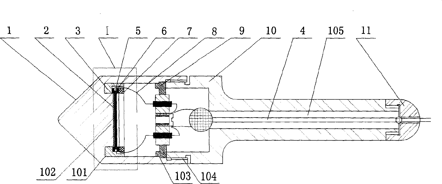
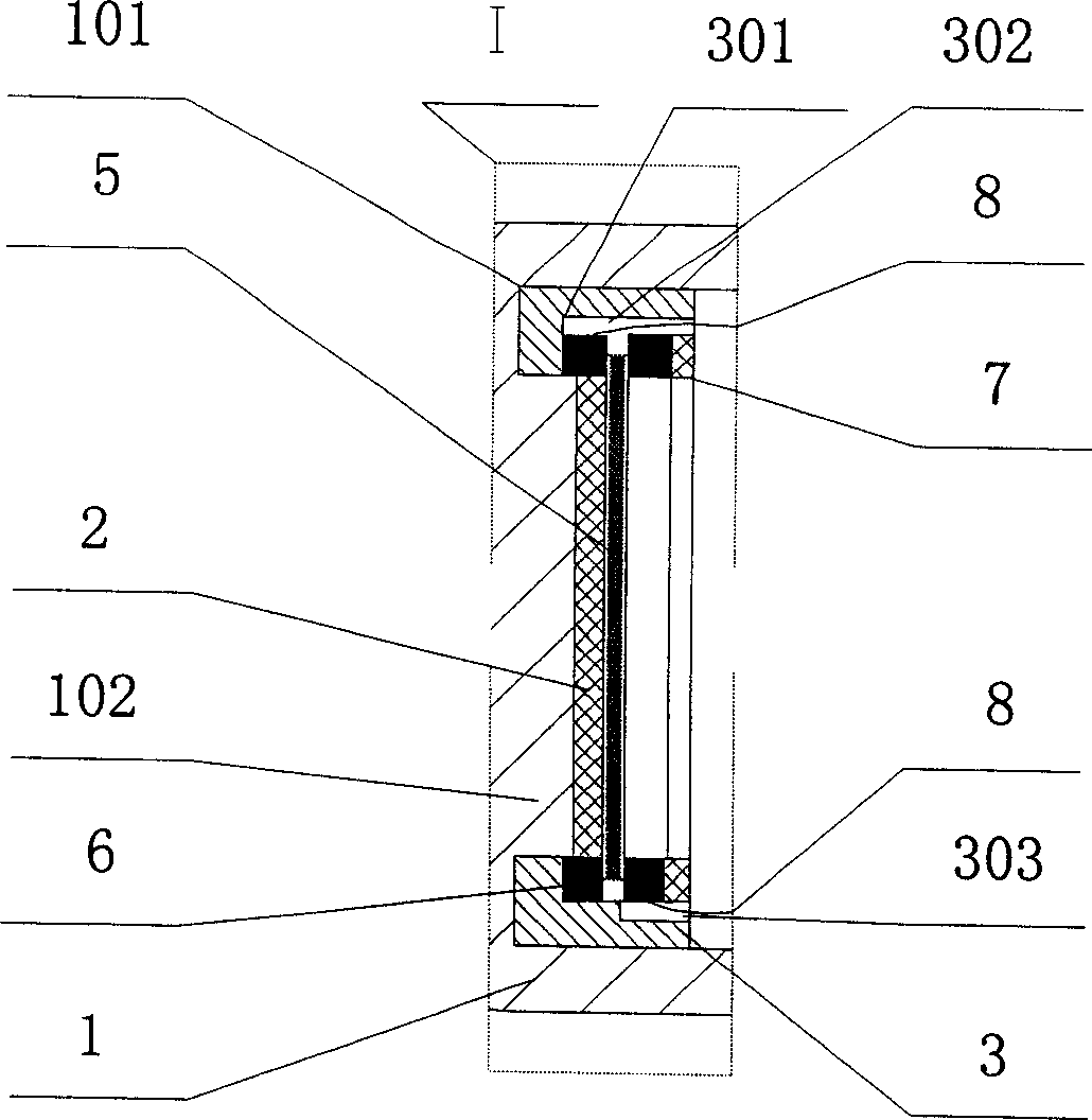
[0024] Piezoelectric acoustic sensor provided by the invention: see figure 1 , figure 2 , image 3 , Figure 4 , Figure 5 , Image 6 , including pickup probe 1, insulating glue 2, insulating seat 3, sensor output line 4, piezoelectric element 5, base electrode 6, insulating seat pressure plate 7, electrode lead wire 8, wire fixing plate 9, hand-held rod 10, sealing cap 11 and other components, the pickup probe 1 picks up the sound signal inside the operating equipment by contacting the outside of the equipment to be tested, and the insulating seat 3 and the insulating seat pressing plate 7 sandwich the piezoelectric element 5 with the base electrode 6 bonded on both sides and make the piezoelectric element 5 The electric element 5 and the base electrode 6 are insulated from the pickup probe 1, the piezoelectric element 5 and the base electrode 6 are bo...


PUM

PropertyMeasurementUnit
Thicknessaaaaaaaaaa

Abstract

A piezoelectric sound sensitive transducer consists of pickup head for picking sound signal up, insulation base and its press plate for placing piezoelectric element with base electrode at middle and for insulating piezoelectric element to pickup head and base electrode, piezoelectric element for picking up sound signal and for converting it to be output electric signal, electrode lead out wire for transmitting said signal to wire fixing plate and transducer output wire for outputting electric signal .

Description

technical field [0001] The invention relates to a piezoelectric sensor, which is mainly used for detecting and monitoring the change of the sound signal when the operating parts of the equipment fail, so as to obtain the information of the complete operation of the equipment. Background technique [0002] Large-scale industrial production uses a large number of machine operating equipment, and the daily maintenance of mechanical equipment is a very important factor to ensure that the equipment is in good condition and thus improve economic benefits. At present, foreign imported equipment and domestic key equipment have basically introduced advanced sensor detection technology and intelligent monitoring system, while the operation status of large reciprocating compressors, pumps, reducers, lathes and other equipment widely used in domestic industrial and mining enterprises mainly Rely on experienced masters to use the method of "seeing, listening and touching" for daily maint...

Claims


Application Information

Patent Timeline
IPC IPC(8): G01H11/08
Inventor 吴斌王庆锋何存富冯喜旺李海涛李伟唐为军
Owner BEIJING UNIV OF TECH
Learn More