
Substrate inspection apparatus

A technology for inspection of substrates and substrates, which is applied to printing devices, measuring devices, components of pumping devices for elastic fluids, etc., can solve the problem of not being able to take pictures of graphics, not being able to clearly distinguish the shade of thin-line graphic grooves, and difficult to obtain Concentration information etc.

Inactive Publication Date: 2005-11-30
DAINIPPON SCREEN MTG CO LTD
View PDF0 Cites 4 Cited by
  • Summary
  • Abstract
  • Description
  • Claims
  • Application Information

AI Technical Summary

Problems solved by technology

[0004] In recent years substrates in which printed patterns have been miniaturized and the surface of the substrate has been treated to make it a smoother plane than in the past due to this miniaturization, it is difficult to cause scattering on the surface of the substrate. In the substrate inspection device described in the New Registration No. 2562299, it is sometimes difficult to obtain clear density information due to the unevenness of the pattern in the CCD line sensor CCD arrangement direction.
As a result, there is a problem that the pattern printed on the substrate cannot be photographed clearly
[0005] For example, in the direction of the scanning movement of the CCD line sensor relative to the substrate (the direction perpendicular to the arrangement direction of the CCD line sensor), there is an unclear The problem of different shades of thin line patterns and grooves (recesses corresponding to gaps between thin lines) between thin line patterns

Method used


Image

  • Substrate inspection apparatus
  • Substrate inspection apparatus
  • Substrate inspection apparatus

Examples


Embodiment Construction

[0028] Next, embodiments of the present invention will be described with reference to the drawings.

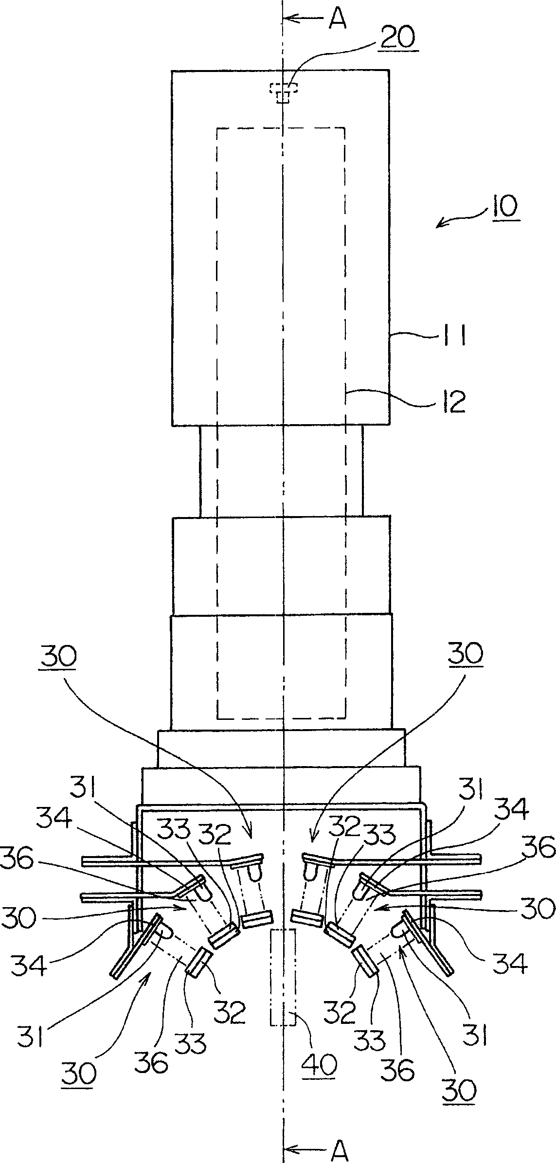
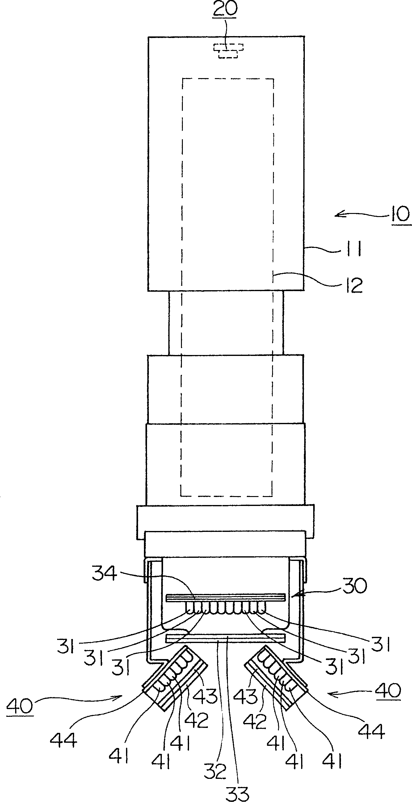
[0029] figure 1 It is a side sectional view showing the camera 10 in the substrate inspection apparatus according to the present invention. also, figure 2 From figure 1 The direction of A-A in FIG. 1 represents a cross-sectional view of the substrate inspection device according to the present invention.

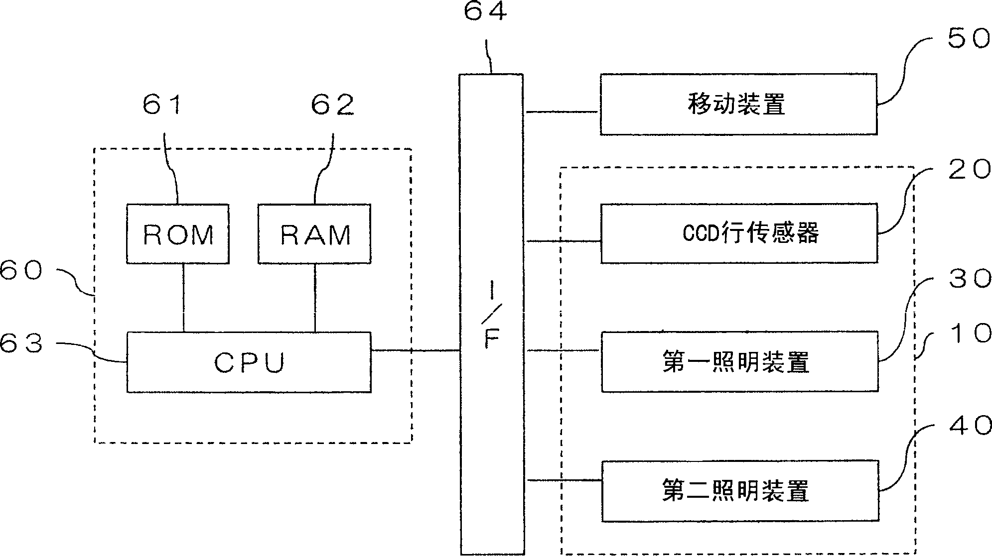
[0030] The substrate inspection device according to the present invention is a device that uses a CCD line sensor 20 in which a plurality of CCDs are arrayed to image a substrate panel, and compares the image data of the surface of the substrate that has been imaged with image data that serves as a predetermined reference. Judging whether the graphics printed on the surface of the substrate are good or not. This substrate inspection apparatus has a camera 10 for imaging the substrate and a moving device 50 for relatively moving the camera 10 relative to the substrate (re...


PUM


Abstract

The objective of the invention is to provide a substrate inspection device capable of clearly imaging the pattern on a substrate. An imaging head 10 is equipped with a CCD line sensor 20, six first illumination means 30 and a pair of second illumination means 40. The second illumination means 40 are arranged on both sides of the LED arranging direction in the first illumination means 30 so that the irradiation angle of the lights emitted from the second illumination means 40 to the surface of the substrate when the lights emitted from the second illumination means 40 are projected on a reference plane abcd is different from the irradiation angle to the surface of the substrate of the lights emitted from the first illumination means 30 when the lights emitted from the first illumination means are projected on the reference plane abcd.

Description

technical field [0001] The present invention relates to a substrate inspection device for judging whether a pattern printed on a substrate is good or not by analyzing an image obtained by imaging the surface of the substrate. Background technique [0002] In the past, as such a substrate inspection apparatus, a substrate inspection apparatus having a structure including a CCD (Charge Coupled Device) line sensor and a CCD arranged in the arrangement direction of the CCD in the CCD line sensor has been known. The linear light source reads the image of the substrate in a rectangular shape by moving these CCD line sensors and the linear light source in the scanning direction relative to the surface of the substrate. Such a conventional substrate inspection apparatus has a problem that accurate density information of an image cannot be obtained when the illuminance distribution of the area illuminated by the CCD line sensor on the substrate is not uniform. [0003] Therefore, as...

Claims


Application Information

Patent Timeline
IPC IPC(8): G01N21/956H04N1/04H05K3/00
CPCF04D29/04F28C1/00F28F25/00F28F27/003
Inventor 水田靖生胁田典宏
Owner DAINIPPON SCREEN MTG CO LTD
Learn More