
Wireless terminal for carrying out visible light short-range communication using camera device

A visible light communication and wireless terminal technology, applied in the field of short-range wireless communication systems

Inactive Publication Date: 2005-11-30
SAMSUNG ELECTRONICS CO LTD
View PDF0 Cites 70 Cited by
  • Summary
  • Abstract
  • Description
  • Claims
  • Application Information

AI Technical Summary

Problems solved by technology

In contrast, other conventional flash modules require a so-called charging delay of about 6 seconds for subsequent shooting

Method used


Image

  • Wireless terminal for carrying out visible light short-range communication using camera device
  • Wireless terminal for carrying out visible light short-range communication using camera device
  • Wireless terminal for carrying out visible light short-range communication using camera device

Examples


Embodiment Construction

[0018] Hereinafter, embodiments of the present invention will be described with reference to the drawings. For conciseness and simplicity, detailed descriptions of known functions and configurations incorporated herein are omitted when it may obscure the subject matter of the present invention.

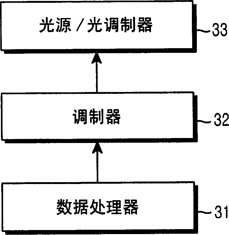
[0019] Referring to Fig. 3a, the transmitter of the visible light short-distance communication system according to the present invention includes: a data processor 31 for processing data; a modulator 32; and a light source / light modulator module 33 for optically modulating the modulated signal for transmission to an external device.

[0020] Referring to Fig. 3b, the receiver of the visible light short-distance communication system according to the present invention includes: an optical sensor 34 for sensing an optical signal transmitted from an external device and converting it into an electrical signal; a demodulator 35 for decoding modulation of the electrical signal from the ligh...


PUM


Abstract

Disclosed is a wireless communication system using visible light and, more particularly, a short-range wireless communication system using a camera sensor module and a flash module mounted on a wireless terminal. The wireless terminal utilizes an LED and a camera sensor selectively for performing camera functions in a wireless terminal and as interface modules for visible light short-range communication.

Description

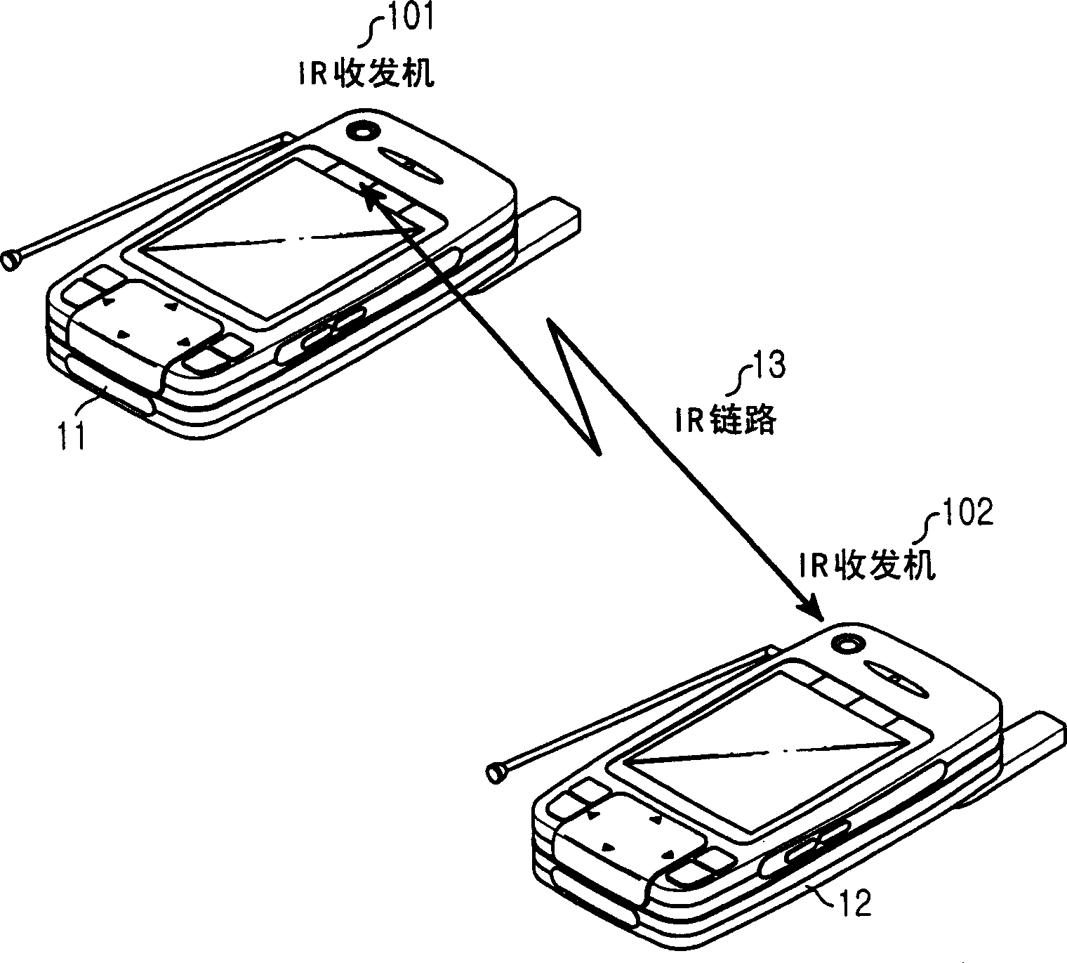
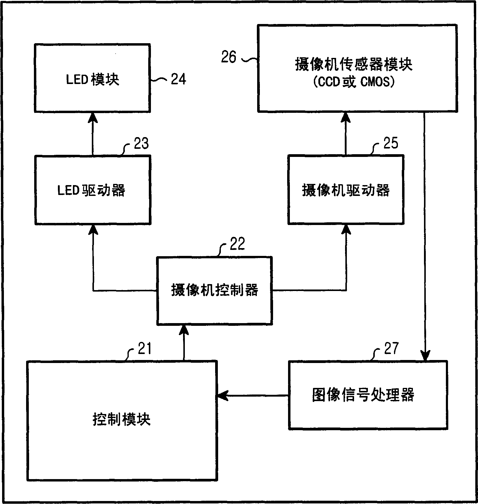
technical field [0001] The present invention relates to a wireless communication system, and more particularly, to a short-distance wireless communication system having a camera sensor module and a flash module installed on a wireless terminal. Background technique [0002] figure 1 A conventional wireless communication system using IR (infrared rays) for short-range communication is shown. As shown, the system utilizing IR employs peer-to-peer (PtoP) communication between wireless terminals 11,12. Each wireless terminal comprises an IR transceiver 101, 102 comprising a transmitter with an LED (Light Emitting Diode) for performing IR transmission, a light modulator, a receiver with a PD (Photodiode) and a demodulator, wherein an IR link 13 is formed when two IR transceivers 101, 102 face each other. [0003] figure 2 is a schematic diagram showing a conventional wireless terminal system. As shown, the system includes a camera sensor module 26 for sensing light signals ...

Claims


Application Information

Patent Timeline
Patent Type & Authority Applications(China)
IPC IPC(8): H04B1/38H04B10/50
CPCH04B1/3827H04B10/116H04B10/502
Inventor 琴智恩李宗和宋在涓李炫又梁承基
Owner SAMSUNG ELECTRONICS CO LTD
Learn More