
Combined building with non-wainscot frame structure and construction method thereof

A frame structure, combined technology, applied in building construction, construction, etc., can solve the difficulty of increasing the amount of scaffolding, formwork and cast-in-place concrete construction management, unreasonable design, procurement, construction methods, and difficulty in adjusting use functions, etc. problems, to achieve the effect of simplifying the contract negotiation process or the bidding and bidding process, the accuracy and specification of orders and customization requirements, great flexibility and variability

Inactive Publication Date: 2005-11-30
刘坚雄
View PDF0 Cites 26 Cited by
  • Summary
  • Abstract
  • Description
  • Claims
  • Application Information

AI Technical Summary

Problems solved by technology

[0002] At present, general house construction usually adopts a mixed frame structure composed of floor (wall), beam, and column. The amount of cast-in-place concrete and the difficulty of construction management, and the cured reinforced concrete floor and walls limit the layout and use of each room, and major changes are not allowed after completion. In addition, the size of the bays is not uniform, which limits each Even if the use of the bay is found to be unreasonable, it is not easy to change it. Due to the limitation of the structure, it is difficult or even impossible to adjust the use function.
In addition, this also brings unreasonable factors to the design, procurement, and construction methods of the project.
In the general house construction process, the designer usually starts the design work after the owner sends out the entrustment, and most of the design work is complicated and non-standard design, because there is not enough time between the owner, designer, and contractor Think, judge and negotiate, so that the design plan, design cycle, construction cycle, and project cost often exceed the expectations of the owner, designer, and contractor, and conflicts often occur between the owner, designer, and contractor. The construction method of construction and modification makes the problems and contradictions more serious

Method used


Image

  • Combined building with non-wainscot frame structure and construction method thereof
  • Combined building with non-wainscot frame structure and construction method thereof
  • Combined building with non-wainscot frame structure and construction method thereof

Examples


Embodiment Construction

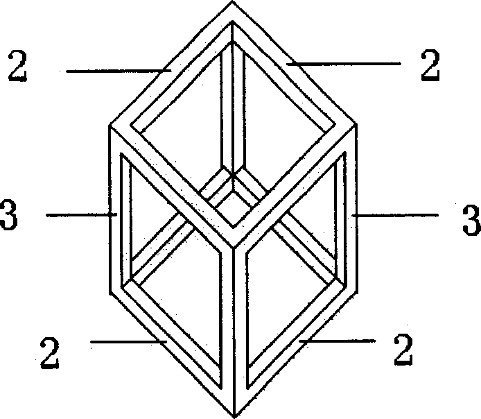
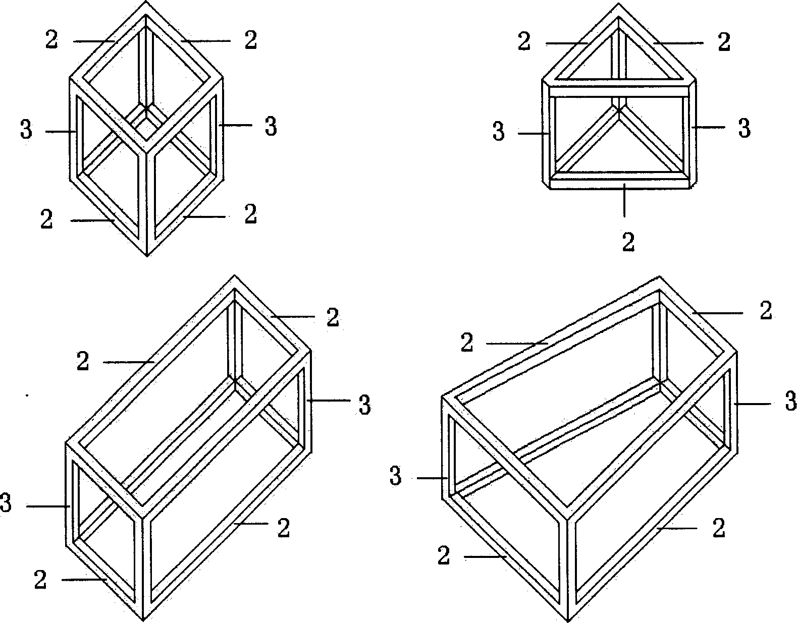
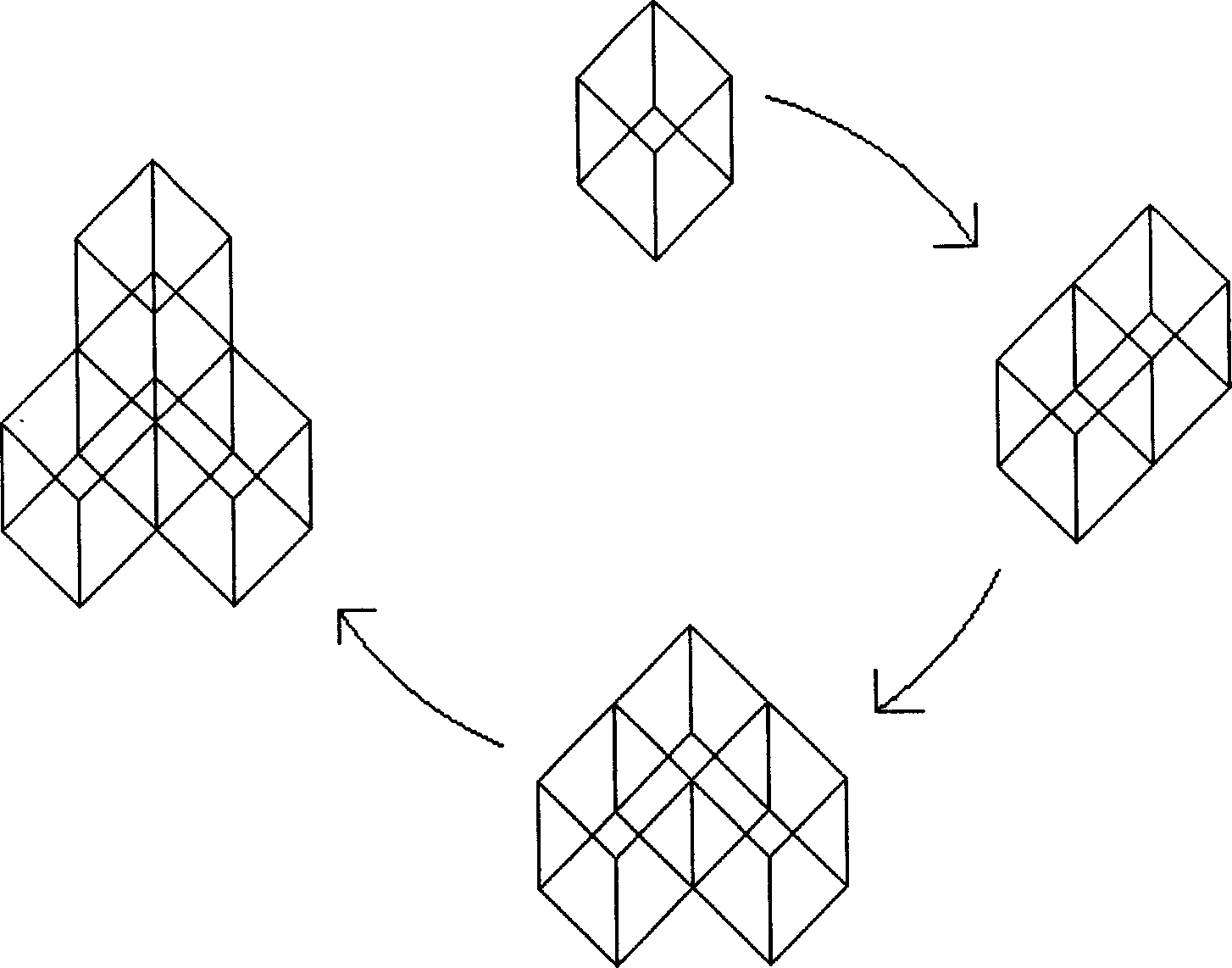
[0032] Figure 1 to Figure 11 Shown is an embodiment of the present invention, including a foundation 1, a hollow frame unit without siding and building elements 4. The foundation 1 can be a natural foundation, a strip foundation, a pile foundation or other foundations capable of supporting the weight of a building. Hollow frame units without siding have one or more such as figure 1 As shown, each hollow frame unit without siding is a cubic frame composed of four beams 2 on the upper floor, four columns 3 in the middle and four beams 2 on the lower floor. The length of the beams 2 is 2 meters to 6 meters. The height of column 3 is 2 meters to 5 meters. The shape and type of these hollow frame units without wall panels can be pre-determined, and can be cubes, cuboids, trapezoidal cubes or triangular cube frames (see figure 2 ). Made of reinforced concrete, concrete, metal, wood or any combination thereof. Such as image 3 and Figure 4 As shown, the frame units without s...


PUM


Abstract

This invention discloses a composite building construction and a method for building it. The construction comprises the base, hollow frame units and the building parts, wherein each hollow frame unit is cube formed from four bridging beams in the topping, four studs in the middle and four bridging beams in the lower, and the hollow frame units are connected with each other which form the space outline of the construction, by which the whole construction has a outline structure without wallboard; the building parts include wall, floor, door, window, roof, theft against wet, feed water equipment, pumping appliance and electrical apparatus, and each building part is matched with the space outline and set inside the outline of the frame.

Description

technical field [0001] The invention relates to a house building with a frame structure and a construction method thereof. Background technique [0002] At present, general house construction usually adopts a mixed frame structure composed of floor (wall), beam, and column. The amount of cast-in-place concrete and the difficulty of construction management, and the cured reinforced concrete floor and walls limit the layout and use of each room, and major changes are not allowed after completion. In addition, the size of the bays is not uniform, which limits each Even if the use of the bay is found to be unreasonable, it is not easy to change it. Due to the limitation of the structure, it is difficult or even impossible to adjust the use function. In addition, this also brings unreasonable factors to the design, procurement, and construction methods of the project. In the general house construction process, the designer usually starts the design work after the owner sends ou...

Claims


Application Information

Patent Timeline
Patent Type & Authority Applications(China)
IPC IPC(8): E04B1/00
Inventor 刘坚雄
Owner 刘坚雄
Learn More