
Compressor installing structure of outdoor unit of one-driven-many indoor unit of air conditioner

An air conditioner room and installation structure technology, applied in the directions of compressors, refrigerators, heating methods, etc., can solve the problems of sparse distribution of pipes, increased weight, and inconvenient installation, so as to reduce manufacturing costs, reduce overall structure, and reduce The effect of production cost

Inactive Publication Date: 2005-11-09
HISENSE HOME APPLIANCES GRP CO LTD
View PDF0 Cites 5 Cited by
  • Summary
  • Abstract
  • Description
  • Claims
  • Application Information

AI Technical Summary

Problems solved by technology

[0003] 1) Since all the compressors are installed flat on one end of the outdoor unit, the plane space occupied by the compressor is relatively large. In this way, the overall space of the outdoor unit is relatively enlarged under the condition that the space of other components of the outdoor unit remains unchanged. The manufacturing cost of the outdoor cabinet increases accordingly
[0004] 2) Since almost all the valve mounting plates of outdoor units on the market are installed at the right end of the box body, the distance between each compressor and the valve mounting plate is relatively large, so the distribution of piping is messy, and the distribution of piping in the space far away from the valve mounting plate is relatively sparse , the distance from the valve mounting plate is close to the space and the piping is dense and prone to interference
[0005] 3) Due to the above two problems, the compatibility of this type of outdoor unit is not too high. For example, one-to-three and one-to-four air-conditioning outdoor units, other structural components should be basically the same, but due to the compressor space The difference in the distribution of the outdoor units and the inconsistent distribution of the piping will make it difficult to use the outdoor unit box body. For example, if the same one is driven by three, when different compressors need to be replaced due to changes in capacity requirements, a similar situation will also occur.
[0006] 4) Generally, there is only one supporting foot on the left and right sides of the bottom of the outdoor unit. Since the weight of one dragging multiple compressors accounts for more than half of the weight of the outdoor unit, and all of them are distributed on the right end of the outdoor unit body, it is best to place the center of gravity of all compressors as close to the right side as possible. Support feet to reduce the deformation of the bottom plate; however, this flat installation makes the distance between some compressors and the support feet relatively large. In order to compensate for the deformation of the bottom plate that may be caused by the insufficient strength of the bottom plate, the bottom plate is generally increased by increasing the thickness of the sheet metal parts of the bottom plate. strength, which increases both weight and cost
[0007] In addition, there are also some outdoor compressors on the market that adopt a double-layer design, but generally speaking, the structure itself is relatively complicated, and it is inconvenient to install during production, so it is difficult to widely promote it.

Method used


Image

  • Compressor installing structure of outdoor unit of one-driven-many indoor unit of air conditioner
  • Compressor installing structure of outdoor unit of one-driven-many indoor unit of air conditioner
  • Compressor installing structure of outdoor unit of one-driven-many indoor unit of air conditioner

Examples


Embodiment 1

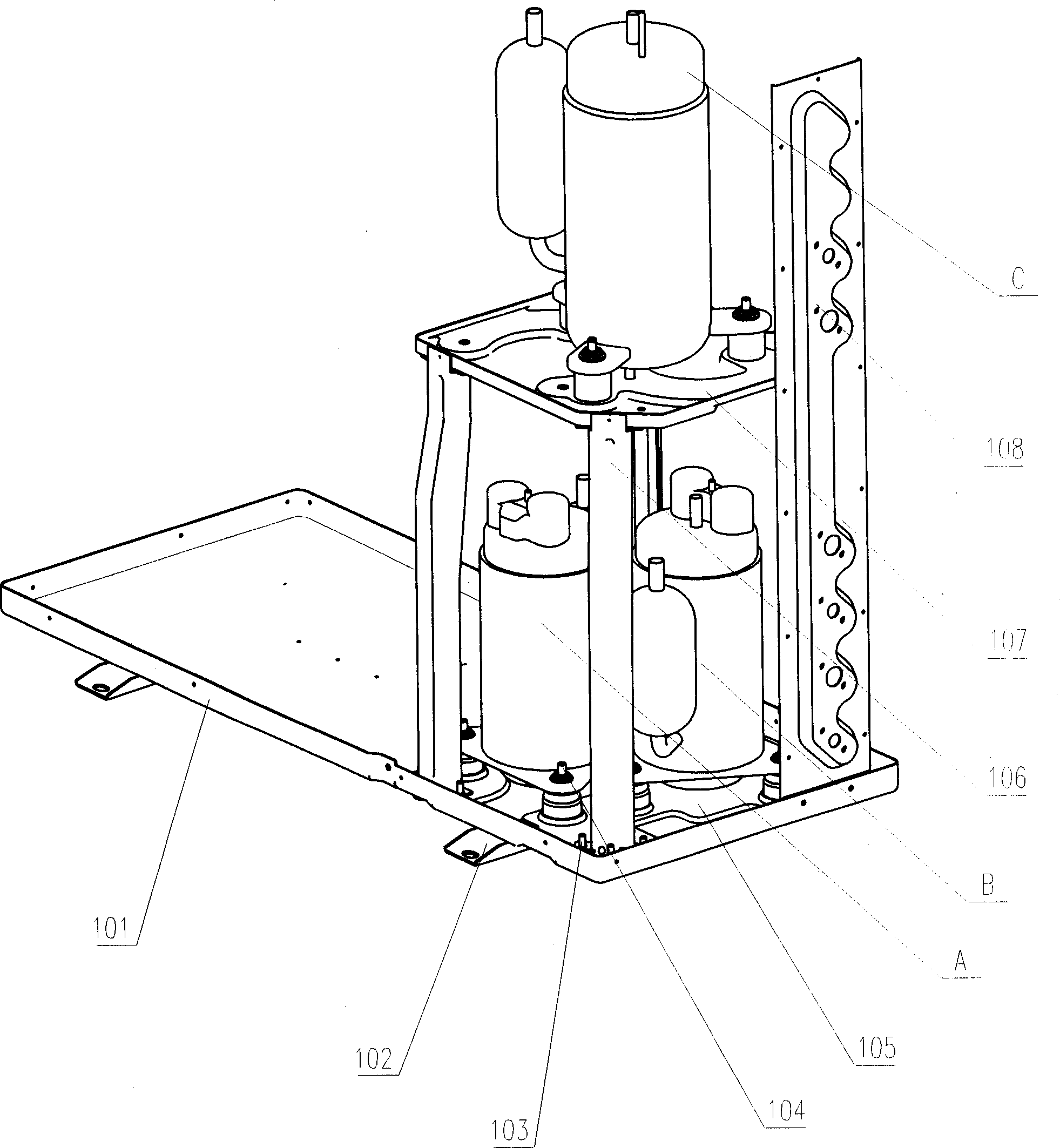
[0029] The structure diagram of the present invention is as figure 1 , 2 , 3, and 4, including bottom plate 1, several fixing screws 4, lower compressor mounting base 5, several support rods 6, upper compressor mounting base 7, several fixing screws 9, and several fixing screws 4 are fixed on the lower compression Machine mounting seat 5, the lower compressor mounting seat 5 is fixed on the bottom plate 1, the upper compressor mounting seat 7 with a number of fixing screws 9 is fixed on the support rod 6, the support rod 6 is fixed on the bottom plate 1, some upper layers Compressor A is fixed on the lower compressor mounting base 5 through nuts that cooperate with fixing screws 4 , and several lower compressors B are fixed on upper compressor mounting bases 7 through nuts that cooperate with fixing screws 9 . There are 1 to 3 upper compressors A, 1 to 3 lower compressors B, and 3 to 6 support rods 6 . In this embodiment, there are two compressors A on the upper floor and on...

Embodiment 2

[0035] The structure diagram of the present invention is as Figure 5 As shown, its structure is the same as that of Embodiment 1, except that there are two compressors A on the upper floor and two compressors B on the lower floor, which are used for one-to-four split air conditioners.


PUM


Abstract

The invention relates to compressor installation structure of outdoor unit of one-drive-plural indoor units of split air conditioner that includes base board, several fixation bolts, down layer compressor installation base, several supporting bar, up layer compressor installation base, and several fixation bolts. The fixation bolts are installed on the down layer compressor installation base, which is fixed on the base board. The up layer compressor installation base is fixed on the supporting bar that is fixed on the base board. Up layer compressor is installed on the down layer compressor installation base. And several down layer compressors are fixed on the up layer compressor installation base. The invention could decrease the space that the compressor takes up. It is simple structure and not easy to cause intervene.

Description

1. Technical field: [0001] The invention relates to a compressor installation structure of an outdoor unit of a one-drag multi-split air conditioner, which belongs to the transformation technology of the compressor installation structure of the outdoor unit of a one-drag multi-split air conditioner. 2. Background technology: [0002] The so-called one-drag multi-split air conditioner generally means that the number of indoor units is 3 or more, that is, the number of outdoor unit compressors is 3 or more. At present, most of the outdoor unit compressors of this type on the market are installed in a single-layer flat style, that is, all compressors are directly installed on one end (usually the right end) of the outdoor unit bottom plate. Such a design has the following disadvantages: [0003] 1) Since all the compressors are installed flat on one end of the outdoor unit, the plane space occupied by the compressor is relatively large. In this way, the overall space of the ou...

Claims


Application Information

Patent Timeline
Patent Type & Authority Applications(China)
IPC IPC(8): F24F13/32
Inventor 梁智文吴晖
Owner HISENSE HOME APPLIANCES GRP CO LTD
Learn More