Hydraulic loop of building machinery

A technology for hydraulic circuits and construction machinery, which is applied in the field of hydraulic circuits and can solve problems such as the inability of pressure oil to be supplied.

Active Publication Date: 2005-11-09
NABLESCO CORP
View PDF2 Cites 4 Cited by
  • Summary
  • Abstract
  • Description
  • Claims
  • Application Information

AI Technical Summary

Problems solved by technology

Therefore, even when the amount of pressure oil used by the directional switching valve for the boom (the first directional switching valve) is sufficient, there is a disadvantage that the pressure oil from the third pump can hardly be supplied.

Method used


Image

  • Hydraulic loop of building machinery
  • Hydraulic loop of building machinery
  • Hydraulic loop of building machinery

Examples


Embodiment Construction

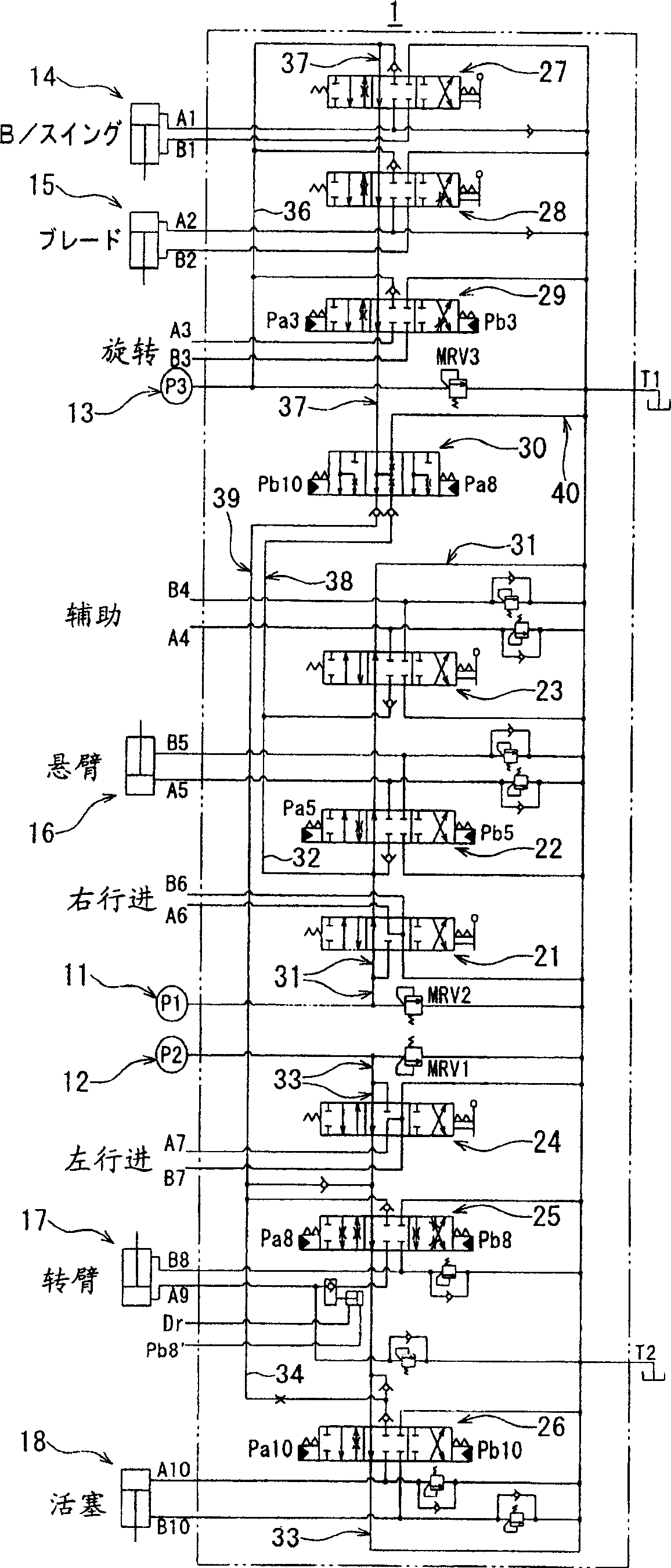
[0023] Hereinafter, preferred embodiments of the present invention will be described with reference to the drawings. figure 1 It is a figure which shows the hydraulic circuit of the construction machine which concerns on embodiment of this invention. The construction machine to which the hydraulic circuit 1 (hereinafter referred to as the hydraulic circuit 1) of the construction machine is applied is a tracked vehicle equipped with various actuators such as a boom or a boom, and has hydraulic motors for driving these actuators. Or each pressure cylinder. Furthermore, this construction machine is equipped with a first pump 11 (P1), a second pump 12 (P2) and a third pump 13 (P3), and the first pump 11 (P1), the second pump 12 (P2) and the The 3 pumps 13 (p3) supply the pressurized oil to the first to third systems provided in the hydraulic circuit 1, respectively.

[0024] Such as figure 1 As shown, the hydraulic circuit 1 is equipped with: a first system, connected with a pl...


PUM


Abstract

The invention efficiently supplys pressure oil from a third pump so as to improve work efficiency of a construction machine by combining it with a first line to which pressure oil from a first pump is supplied, and a second line to which pressure oil from a second pump is supplied. In a first combined flow passage 38, pressure oil from the third pump 13 can be supplied to a first unloading passage 31 in the first line. In a second combined flow passage 39, pressure oil from the third pump 13 can be supplied to a second supply passage 34 in the second line. In a discharge passage 40, a restrictor is formed, and the first combined flow passage 38, the second combined flow passage 39, and a tank are connected.

Description

technical field [0001] The present invention relates to a hydraulic circuit of a construction machine, which is provided with: a first system including a first directional switching valve supplied with pressure oil from a first pump; a second system including a pressure oil supplied from a second pump The second directional switching valve; the third system includes a third directional switching valve supplied with pressure oil from the third pump. Background technique [0002] As a hydraulic circuit of a conventional construction machine, generally, there are: a first system including: a first directional switching valve supplied with pressure oil from a first pump; a second system, the second system Including: the second directional switching valve, which is supplied with the pressure oil from the second pump; the third system, which includes: the third directional switching valve, which is supplied with the pressure oil from the third pump (refer to Patent Document 1, 2,...

Claims


Application Information

Patent Timeline
IPC IPC(8): E02F9/22F15B11/02F15B11/16F15B11/17
CPCH04M1/0264H01R31/06H04N23/51
Inventor 井奥贤介濑川均
Owner NABLESCO CORP
Why Eureka
Try Eureka